
Page 213 - Rashid, Power Electronics Handbook
P. 213
202 J. W. Dixon
written for unity power factor operation. In such a case V I S
cos j ¼ 1, and sin j ¼ 0:
w
p dI
n ðtÞ¼ V 2 ÿ RI ÿ L max sin ot
MOD max S
dt
ÿ X I Þ cos ot ð12:66Þ w
S max
With this last equation, a unity power factor, voltage source,
voltage controlled PWM recti®er can be implemented as
shown in Fig. 12.49. It can be observed that Eqs. (12.65)
and (12.66) have an in-phase term with the mains supply
(sin ot), and an in-quadrature term (cos ot). These two terms w
allow the template V to change in magnitude and phase so
MOD
as to have full unity power factor control of the recti®er.
Compared with the control block of Fig. 12.43, in the
voltage-source voltage-controlled recti®er of Fig. 12.49, there w
is no need to sense the input currents. However, to ensure
stability limits as good as the limits of the current-controlled
recti®er, blocks ‘‘ÿRÿsL '' and ‘‘ÿx '' in Fig. 12.49 have to
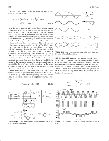
s S FIGURE 12.50 Steady-state operation of the unity power factor recti-
emulate and reproduce exactly the real values of R, X , and L S ®er, under different load conditions.
S
of the power circuit. However, these parameters do not remain
constant, and this fact affects the stability of this system, With the sinusoidal template V MOD already created, a modu-
making it less stable than the system shown in Fig. 12.43. In lation method to commutate the transistors will be required.
theory, if the impedance parameters are reproduced exactly, As in the case of the current-controlled recti®er, there are
the stability limits of this recti®er are given by the same many methods to modulate the template, with the most well
equations as used for the current-controlled recti®er seen in known the so-called sinusoidal pulse width modulation
Fig. 12.43 (Eqs. (12.57) and (12.58). (SPWM), which uses a triangular carrier to generate the
Under steady-state, I max is constant, and Eq. (12.66) can be PWM as shown in Fig. 12.51. Only this method will be
written in terms of phasor diagram, resulting in Eq. (12.67). described in this chapter.
As shown in Fig. 12.50, different operating conditions for the
unity power factor recti®er can be displayed with this equa-
tion:
~
~
~
V MOD ¼ V ÿ RI ÿ jX I ~ ð12:67Þ
s S
S
v = V M sin wt A
A
L S R
i s
B
v B i s
C C
v I s
FIGURE 12.49 Implementation of the voltage-controlled recti®er for FIGURE 12.51 Sinusoidal modulation method based on triangular
unity power factor operation. carrier.