
Page 209 - Rashid, Power Electronics Handbook
P. 209
198 J. W. Dixon
i s
V
I S L S
V MOD
i Tn
i Dp
Control Block
i dc
V I S
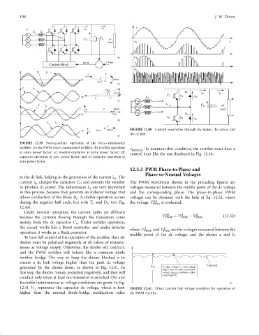
FIGURE 12.40 Current waveforms through the mains, the valves, and
the dc link.
FIGURE 12.39 Four-quadrant operation of the force-commutated
recti®er: (a) the PWM force-commutated recti®er; (b) recti®er operation n . To maintain this condition, the recti®er must have a
at unity power factor; (c) inverter operation at unity power factor; (d) BRIDGE
control loop like the one displayed in Fig. 12.36.
capacitor operation at zero power factor; and (e) inductor operation at
zero power factor.
12.3.3 PWM Phase-to-Phase and
Phase-to-Neutral Voltages
to the dc link, helping in the generation of the current i . The
dc
current i dc charges the capacitor C and permits the recti®er The PWM waveforms shown in the preceding ®gures are
D
to produce dc power. The inductances L are very important voltages measured between the middle point of the dc voltage
S
in this process, because they generate an induced voltage that and the corresponding phase. The phase-to-phase PWM
allows conduction of the diode D . A similar operation occurs voltages can be obtained with the help of Eq. 12.52, where
P
AB
during the negative half cycle, but with T and D (see Fig. the voltage V PWM is evaluated,
P
N
12.40).
Under inverter operation, the current paths are different AB A B
because the currents ¯owing through the transistors come V PWM ¼ V PWM ÿ V PWM ð12:52Þ
mainly from the dc capacitor C . Under recti®er operation,
D
the circuit works like a Boost converter, and under inverter where V A , and V B are the voltages measured between the
PWM
PWM
operation it works as a Buck converter. middle point of the dc voltage, and the phases a and b,
To have full control of the operation of the recti®er, their six
diodes must be polarized negatively at all values of instanta-
neous ac voltage supply. Otherwise, the diodes will conduct,
and the PWM recti®er will behave like a common diode
recti®er bridge. The way to keep the diodes blocked is to
ensure a dc link voltage higher than the peak dc voltage
generated by the diodes alone, as shown in Fig. 12.41. In BRIDGE
this way, the diodes remain polarized negatively, and they will BRIDGE
conduct only when at least one transistor is switched ON, and
favorable instantaneous ac voltage conditions are given. In Fig.
12.41 V D represents the capacitor dc voltage, which is kept FIGURE 12.41 Direct current link voltage condition for operation of
higher than the normal diode-bridge recti®cation value the PWM recti®er.