
Page 204 - Rashid, Power Electronics Handbook
P. 204
12 Three-Phase Controlled Recti®ers 193
v A
2. they can help in stability problems related with subsyn-
v B
chronous resonance in long ac lines;
v C
3. they have very good dynamic behavior, and can inter-
rupt short-circuits problems very quickly;
4. if transmission is by submarine or underground cable,
it is not practical to consider ac cable systems exceed-
ing 50 km, but dc cable transmission systems are in
service whose length is in hundreds of kilometers and
even distances of 600 km or greater have been consid-
ered feasible;
5. reversal of power can be controlled electronically by
FIGURE 12.28 Supersynchronous cascade for a wound rotor induction
means of the delay ®ring angles a;
motor.
6. some existing overhead ac transmission lines cannot be
increased. If overbuilt with or upgraded to dc trans-
mission this can substantially increase the power
12.2.11 Applications in HVDC Power
Transmission transfer capability on the existing right-of-way.
The use of HVDC systems for interconnections of asyn-
High voltage direct current (HVDC) power transmission is the
chronous systems is an interesting application. Some conti-
most powerful application for line-commutated converters
nental electric power systems consist of asynchronous
that exist today. There are power converters with ratings in
networks such as those for the East-West Texas and Quebec
excess of 1000 MW. Series operation of hundreds of valves can
networks in North America, and island loads such as that for
be found in some HVDC systems. In high-power and long
the Island of Gotland in the Baltic Sea make good use of
distance applications, these systems become more economical
HVDC interconnections.
than conventional ac systems. They also have some other
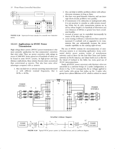
Nearly all HVDC power converters with thyristor valves are
advantages compared with ac systems:
assembled in a converter bridge of 12-pulse con®guration, as
1. they can link two ac systems operating unsynchronized shown in Fig. 12.29. Consequently, the ac voltages applied to
or with different nominal frequencies, that is each 6-pulse valve group that makes up the 12-pulse valve
50 Hz $ 60 Hz; group have a phase difference of 30 which is utilized to cancel
POWER I D
SYSTEM 1
Y D
V D
FIGURE 12.29 Typical HVDC power system. (a) Detailed circuit; and (b) unilinear diagram.