
Page 199 - Rashid, Power Electronics Handbook
P. 199
188 J. W. Dixon
I D
L D
v A i A
i B
v B
v D
V D
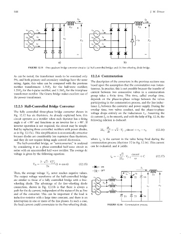
FIGURE 12.15 One-quadrant bridge converter circuits: (a) half-controlled bridge; and (b) free-wheeling diode bridge.
As can be noted, the transformer needs to be oversized only 12.2.6 Commutation
5%, and both primary and secondary windings have the same
The description of the converters in the previous sections was
rating. Again, this value can be compared with the previous
based upon the assumption that the commutation was instan-
recti®er transformers: 1:35P D for the half-wave recti®er; taneous. In practice, this is not possible because the transfer of
1:55P for the 6-pulse recti®er; and 1:26P for the interphase current between two consecutive valves in a commutation
D
D
transformer recti®er. The Graetz bridge makes excellent use of
group takes a ®nite time. This time, called overlap time,
the power transformer.
depends on the phase-to-phase voltage between the valves
participating in the commutation process, and the line induc-
12.2.5 Half-Controlled Bridge Converter tance L between the converter and power supply. During the
S
overlap time, two valves conduct, and the phase-to-phase
The fully controlled three-phase bridge converter shown in
voltage drops entirely on the inductances L . Assuming the
S
Fig. 12.12 has six thyristors. As already explained here, this
dc current I to be smooth, and with the help of Fig. 12.16, the
D
circuit operates as a recti®er when each thyristor has a ®ring following relation is deduced:
angle a of <90 and functions as an inverter for a >90 .If
inverter operation is not required, the circuit may be simpli-
di sc p
®ed by replacing three controlled recti®ers with power diodes, 2L ¼ 2 V sin ot ¼ n ÿ n ð12:16Þ
S f ÿf A B
as in Fig. 12.15a). This simpli®cation is economically attractive dt
because diodes are considerably less expensive than thyristors,
and they do not require ®ring angle control electronics. where i sc is the current in the valve being ®red during the
The half-controlled bridge, or ‘‘semiconverter,'' is analyzed commutation process (thyristor T2 in Fig. 12.16). This current
by considering it as a phase-controlled half-wave circuit in can be evaluated, and it yields:
series with an uncontrolled half-wave recti®er. The average dc
p
voltage is given by the following equation: 2 cos ot
i ¼ÿ V f ÿf þ C ð12:17Þ
sc
p 2L S o
sec
3 2 V f ÿf
V ¼ ð1 þ cos aÞ ð12:15Þ
D
2p ON
OFF
Then, the average voltage V D never reaches negative values.
The output voltage waveforms of the half-controlled bridge T1
v A L S
are similar to those of a fully controlled bridge with a free-
wheeling diode. The advantage of the free-wheeling diode
connection, shown in Fig. 12.15b is that there is always a
path for the dc current, independent of the status of the ac line
and of the converter. This can be important if the load is
inductive-resistive with a large time constant, and there is an
interruption in one or more of the line phases. In such a case,
the load current could commutate to the free-wheeling diode. FIGURE 12.16 Commutation process.