
Page 197 - Rashid, Power Electronics Handbook
P. 197
186 J. W. Dixon
12.2.3 Double Star Rectifier with Interphase
Connection
This topology works as two half-wave recti®ers in parallel, and
is very useful when high dc current is required. An optimal
way to reach both good balance and eliminaton of harmonics
is through the connection shown in Fig. 12.8. The two
recti®ers are shifted by 180 , and their secondary neutrals
are connected through a middle-point autotransformer, called
an ‘‘interphase transformer''. The interphase transformer is
connected between the two secondary neutrals, and the middle
point at the load return. In this way, both groups operate in
parallel. Half the direct current ¯ows in each half of the
interphase transformer and then its iron core does not
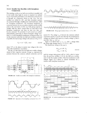
FIGURE 12.10 Firing angle variation from a ¼ 0 to 180 .
become saturated. The potential of each neutral can oscillate
independently, generating an almost triangular voltage wave-
form (v ) in the interphase transformer, as shown in Fig. 12.9. neutral N1. The voltage n D2 is between the common cathode
T
As this converter works like two half-wave recti®ers connected connection and N2. It can be seen that the two instantaneous
in parallel, the load average voltage is the same as in Eq. (12.1): voltages are shifted, which gives as a result a voltage n that is
D
smoother than n D1 and n .
D2
Figure 12.10 shows how n , n , n and n change when
V 1:17 V rms cos a ð12:10Þ D D1 D2 T
D f ÿN the ®ring angle changes from a ¼ 0 to a ¼ 180 .
The transformer rating in this case is
where V rms is the phase-to-neutral rms voltage at the valve
f ÿN
side of the transformer (secondary). VA prim ¼ 1:05 P D
The Fig. 12.9 also shows the two half-wave recti®er voltages, VA sec ¼ 1:48 P D ð12:11Þ
related to their respective neutrals. Voltage n represents the
D1
potential between the common cathode connection and the
and the average rating power will be 1:26P , which is better
D
than the previous recti®ers (1.35 for the half-wave recti®er,
and 1.55 for the 6-pulse recti®er). Thus the transformer is well
utilized. Figure 12.11 shows ac current waveforms for a
v T
recti®er with interphase transformer.
D
i A
v A i A
a
I D
v a v 3 v b v 1
FIGURE 12.8 Double star recti®er with interphase transformer. i a I D/2
i b
i c
v a
i 1
i a
FIGURE 12.11 AC current waveforms for the recti®er with interphase
FIGURE 12.9 Operation of the interphase connection for a ¼ 0 . transformer.