Page 192 - Rashid, Power Electronics Handbook
P. 192

11  Single-Phase Controlled Recti®ers                                                               181

                                                                                          THY SW
                                                    Converter               Inverter
                                                                                     THY1


                             R                                                                  TR1
                                                                                                    THY2
                         +
                             S
                            Input
                            1f100 V                                                                       Output
                                                                                                          1f100 V

                                                  FIGURE 11.28  Single-phase UPS with PWM recti®er.


                                                           I
                                                            d


                                i
                                s

                          V                                  V d                                       3~
                           s


                              Line + transformer  4-quadrant-converter  DC  -  Link  Inverter        Motor
                                            FIGURE 11.29  Typical power circuit of an ac drive for a locomotive.

                                                                       OVERHEAD  PWM
                                                                       CATENARY  CONVERTER  SMOOTHING CAPACITOR
                   Perhaps the most typical and widely accepted area of
                 application of high-power factor single-phase recti®ers is in
                                                                                                                INDUCTION
                 locomotive drives [6]. In effect, an essential prerequisite for                   PWM INVERTER  MOTORS
                 proper operation of voltage source three-phase inverter drives
                 in modern locomotives is the use of four quadrant
                 line-side converters, which ensures motoring and braking of
                 the drive, with reduced harmonics in the input current.
                 Figure 11.29 shows a simpli®ed power circuit of a typical
                 drive for a locomotive connected to a single-phase power
                 supply [6], which includes a high-power factor recti®er at the  TRANSFORMER
                 input.
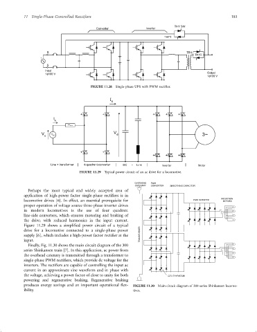
                   Finally, Fig. 11.30 shows the main circuit diagram of the 300
                 series Shinkansen train [7]. In this application, ac power from
                 the overhead catenary is transmitted through a transformer to
                 single-phase PWM recti®ers, which provide dc voltage for the
                 inverters. The recti®ers are capable of controlling the input ac
                 current in an approximate sine waveform and in phase with
                 the voltage, achieving a power factor of close to unity for both      GTO THYRISTOR
                 powering and regenerative braking. Regenerative braking
                 produces energy savings and an important operational ¯ex-  FIGURE 11.30  Main circuit diagram of 300 series Shinkansen locomo-
                 ibility.                                             tives.
   187   188   189   190   191   192   193   194   195   196   197