Page 196 - Rashid, Power Electronics Handbook
P. 196

12  Three-Phase Controlled Recti®ers                                                                185

                 and                                                  voltage is higher than that from the half-wave recti®er, and its
                                                                      average value is given by
                                              rms
                                V ¼ 1:17   a   V ðprimÞf ÿN    ð12:4Þ
                                  D
                                                                                   ð p=6þa
                                                                               V max
                                                                          V ¼             cos ot   dðotÞ
                                                                           D
                 where a is the secondary to primary turn relation of the       p=3  ÿp=6þa
                 transformer. On the other hand, a relation between the            sin p=6             rms    cos a
                 currents is also possible to obtain. With the help of Fig. 12.5,  ¼ V max  p=6    cos a   1:35   V f ÿN  ð12:8Þ
                                           I D
                                     rms
                                    I   ¼ p                    ð12:5Þ  The dc voltage ripple is also smaller than the one generated by
                                     sec    
                                            3                         the half-wave recti®er, due to the absence of the third
                                              p 
                                             I D  2                   harmonic with its inherently high amplitude. The smoothing
                                     rms
                                    I   ¼ a                    ð12:6Þ
                                     prim                             reactor L is also considerably smaller than the one needed for
                                              3                              D
                                                                      a 3-pulse (half-wave) recti®er.
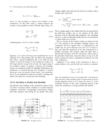
                                                                        The ac currents of the 6-pulse recti®er are shown in Fig.
                 Combining Eqs. (12.2) to (12.6), it yields
                                                                      12.7. The currents in the secondary windings present a dc
                                                                      component, but the magnetic ¯ux is compensated by the
                                   VA prim  ¼ 1:21   P D              double star. As can be observed, only one valve is ®red at a
                                                               ð12:7Þ
                                    VA   ¼ 1:48   P                   time, and then this connection in no way corresponds to a
                                       sec       D
                                                                      parallel connection. The currents inside the delta show a

                                                                      symmetrical waveform, with 60 conduction. Finally, due to
                 Equation (12.7) shows that the power transformer has to be  the particular transformer connection shown in Fig. 12.6, the
                 oversized 21% at the primary side, and 48% at the secondary  source currents also show a symmetrical waveform, but with

                 side. Then a special transformer has to be built for this  120 conduction.
                 recti®er. In terms of average VA, the transformer needs to be  Evaluation of the rating of the transformer is done in
                 35% larger that the rating of the dc load. The larger rating of  similar fashion to the way the half-wave recti®er is evaluated:
                 the secondary respect to primary is because the secondary
                 carries a dc component inside the windings. Furthermore, the
                                                                                        VA    ¼ 1:28   P
                 transformer is oversized because the circulation of current              prim        D            ð12:9Þ
                 harmonics does not generate active power. Core saturation,              VA sec  ¼ 1:81   P D
                 due to the dc components inside the secondary windings, also
                 needs to be taken into account for iron oversizing.
                                                                      Thus, the transformer must be oversized 28% at the primary
                                                                      side, and 81% at the secondary side. In terms of size it has an
                                                                      average apparent power of 1.55 times the power P  (55%
                 12.2.2 Six-Pulse or Double Star Rectifier                                                         D
                                                                      oversized). Because of the short conducting period of the
                 The thyristor side windings of the transformer shown in Fig.  valves, the transformer is not particularly well utilized.
                 12.6 form a six-phase system, resulting in a 6-pulse starpoint
                 (midpoint connection). Disregarding commutation overlap,           a

                 each valve conducts only during 60 per period. The direct
                                                                              I D
                                                                                                               w
                                                                                 v a  v 3  v b  v 1  v c
                                                                              i a
                                                                              i b
                             D
                             i A
                   v A  i A


                               FIGURE 12.6  Six-pulse recti®er.          FIGURE 12.7  AC current waveforms for the 6-pulse recti®er.
   191   192   193   194   195   196   197   198   199   200   201