
Page 198 - Rashid, Power Electronics Handbook
P. 198
12 Three-Phase Controlled Recti®ers 187
12.2.4 Three-Phase Full-Wave Rectifier or
v c a v a v b
Graetz Bridge
Parallel connection via interphase transformers permits the I D
implementation of recti®ers for high current applications.
Series connection for high voltage is also possible, as shown
v D
in the full-wave recti®er of Fig. 12.12. With this arrangement, A2
A1
it can be seen that the three common cathode valves generate a
positive voltage with respect to the neutral, and the three
common anode valves produce a negative voltage. The result is
a dc voltage twice the value of the half-wave recti®er. Each half
of the bridge is a 3-pulse converter group. This bridge
connection is a two-way connection, and alternating currents w
¯ow in the valve-side transformer windings during both half
periods, avoiding dc components into the windings, and
saturation in the transformer magnetic core. These character-
istics make the so-called Graetz bridge the most widely used FIGURE 12.13 Voltage waveforms for the Graetz bridge.
line-commutated thyristor recti®er. The con®guration does
not need any special transformer, and works as a 6-pulse
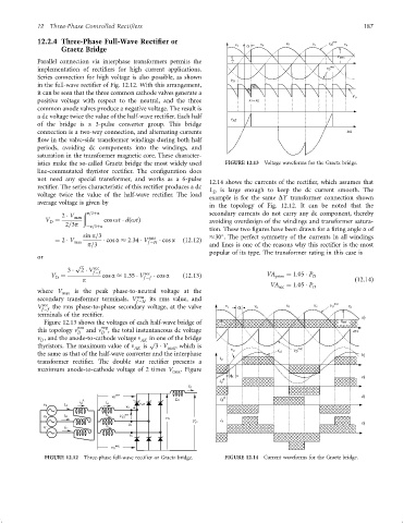
12.14 shows the currents of the recti®er, which assumes that
recti®er. The series characteristic of this recti®er produces a dc
L D is large enough to keep the dc current smooth. The
voltage twice the value of the half-wave recti®er. The load
example is for the same DY transformer connection shown
average voltage is given by
in the topology of Fig. 12.12. It can be noted that the
ð p=3þa secondary currents do not carry any dc component, thereby
2 V max
V ¼ 2=3p cos ot dðotÞ avoiding overdesign of the windings and transformer satura-
D
ÿp=3þa
tion. These two ®gures have been drawn for a ®ring angle a of
sin p=3 rms 30 . The perfect symmetry of the currents in all windings
¼ 2 V cos a 2:34 V cos a ð12:12Þ
max f ÿN
p=3 and lines is one of the reasons why this recti®er is the most
popular of its type. The transformer rating in this case is
or
p
sec
3 2 V f ÿf
V ¼ cos a 1:35 V sec cos a ð12:13Þ VA prim ¼ 1:05 P D
D p f ÿf ð12:14Þ
VA sec ¼ 1:05 P D
where V max is the peak phase-to-neutral voltage at the
rms
secondary transformer terminals, V f ÿN its rms value, and
V sec the rms phase-to-phase secondary voltage, at the valve v c a v a v b
f ÿf
terminals of the recti®er.
Figure 12.13 shows the voltages of each half-wave bridge of I D
this topology n pos and n neg , the total instantaneous dc voltage w
D D
v , and the anode-to-cathode voltage n AK in one of the bridge
D
thyristors. The maximum value of n AK is p 3 V max , which is
v a i a1
the same as that of the half-wave converter and the interphase
i a
transformer recti®er. The double star recti®er presents a
maximum anode-to-cathode voltage of 2 times V max . Figure
pos
v D
D
i A i a
v A i A
i b
i B
FIGURE 12.12 Three-phase full-wave recti®er or Graetz bridge. FIGURE 12.14 Current waveforms for the Graetz bridge.