
Page 187 - Rashid, Power Electronics Handbook
P. 187
176 J. Rodrõ Âguez and A. Weinstein
2500
2000
1500
Amplitude mA
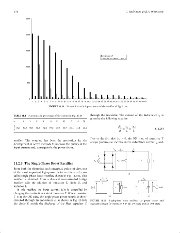
Standard IEC 1000-3-2 Class D
1000
500
0
1 2 3 4 5 6 7 8 9 10 11 12 13 14 15 16 17 18 19 20 21 22 23 24 25 26 27 28 29 30 31 32 33 34 35 36 37 38 39 40
FIGURE 11.15 Harmonics in the input current of the recti®er of Fig. 11.14.
TABLE 11.1 Harmonics in percentage of the current in Fig. 11.14 through the transistor. The current of the inductance i is
L
given by the following equation
n 3 5 7 9 11 13 15 17 19 21
I n di L v L jv j
s
[%] 96.8 90.5 81.7 71.0 59.3 47.3 35.7 25.4 16.8 10.6 ¼ ¼ ð11:26Þ
dt L L
I 1
Due to the fact that jv j > 0, the ON state of transistor T
s
recti®er. This standard has been the motivation for the
always produces an increase in the inductance current i and,
L
development of active methods to improve the quality of the
input current and, consequently, the power factor.
i D
L L
i
s
v s + |v s | X C V o
11.2.3 The Single-Phase Boost Rectifier
From both the theoretical and conceptual points of view, one
of the most important high-power factor recti®ers is the so-
a)
called single-phase boost recti®er, shown in Fig. 11.16a. This
v v
recti®er is obtained from a classical noncontrolled bridge L i L L
recti®er, with the addition of transistor T, diode D, and L L
V 0
inductor L. v v s V Load
s C Load C 0
In this recti®er, the input current i ðtÞ is controlled by
s
changing the conduction state of transistor T. When transistor
T is in the ON state, the single-phase power supply is short- b) c)
circuited through the inductance L, as shown in Fig. 11.16b; FIGURE 11.16 Single-phase boost recti®er: (a) power circuit and
the diode D avoids the discharge of the ®lter capacitor C equivalent circuit for transistor T in (b) ON-state and (c) OFF-state.