
Page 185 - Rashid, Power Electronics Handbook
P. 185
174 J. Rodrõ Âguez and A. Weinstein
i
d
i v T1 T T
s L 1 3
L Grid Load
+ d
v v
s d
V L
T T
4 2
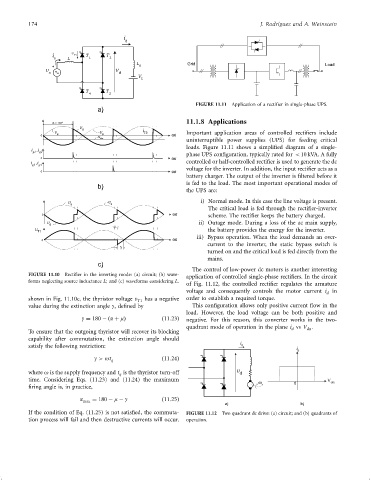
FIGURE 11.11 Application of a recti®er in single-phase UPS.
a)
11.1.8 Applications
a= 135º
v
v d -v i T3 Important application areas of controlled recti®ers include
0 s s wt
uninterruptible power supplies (UPS) for feeding critical
V dia
loads. Figure 11.11 shows a simpli®ed diagram of a single-
i ,i
g1 g2
phase UPS con®guration, typically rated for < 10 kVA. A fully
0 wt
i ,i controlled or half-controlled recti®er is used to generate the dc
g3 g4
voltage for the inverter. In addition, the input recti®er acts as a
0 wt
battery charger. The output of the inverter is ®ltered before it
is fed to the load. The most important operational modes of
b)
the UPS are:
v s -v s i) Normal mode. In this case the line voltage is present.
The critical load is fed through the recti®er-inverter
0 wt scheme. The recti®er keeps the battery charged.
v ii) Outage mode. During a loss of the ac main supply,
d m
v T1 the battery provides the energy for the inverter.
iii) Bypass operation. When the load demands an over-
0 wt
current to the inverter, the static bypass switch is
g
turned on and the critical load is fed directly from the
mains.
c)
The control of low-power dc motors is another interesting
FIGURE 11.10 Recti®er in the inverting mode: (a) circuit; (b) wave-
application of controlled single-phase recti®ers. In the circuit
forms neglecting source inductance L; and (c) waveforms considering L.
of Fig. 11.12, the controlled recti®er regulates the armature
voltage and consequently controls the motor current i in
d
shown in Fig. 11.10c, the thyristor voltage v T1 has a negative order to establish a required torque.
value during the extinction angle g, de®ned by This con®guration allows only positive current ¯ow in the
load. However, the load voltage can be both positive and
g ¼ 180 ÿða þ mÞ ð11:23Þ negative. For this reason, this converter works in the two-
quadrant mode of operation in the plane i vs V .
da
d
To ensure that the outgoing thyristor will recover its blocking
capability after commutation, the extinction angle should
i
satisfy the following restriction: d
i
d
g > ot q ð11:24Þ
where o is the supply frequency and t is the thyristor turn-off v d
q
time. Considering Eqs. (11.23) and (11.24) the maximum V
w 0 da
®ring angle is, in practice, r
a max ¼ 180 ÿ m ÿ g ð11:25Þ
a) b)
If the condition of Eq. (11.25) is not satis®ed, the commuta- FIGURE 11.12 Two quadrant dc drive: (a) circuit; and (b) quadrants of
tion process will fail and then destructive currents will occur. operation.