
Page 180 - Rashid, Power Electronics Handbook
P. 180
11
Single-Phase Controlled Recti®ers
Jose  Rodrõ Âguez, Ph.D. and 11.1 Line Commutated Single-Phase Controlled Recti®ers................................. 169
Alejandro Weinstein, Ph.D. 11.1.1 Single-Phase Half-Wave Recti®er 11.1.2 Biphase Half-Wave Recti®er
Department of Electronics, 11.1.3 Single-Phase Bridge Recti®er 11.1.4 Analysis of the Input Current 11.1.5 Power
Universidad Te Âcnica Factor of the Recti®er 11.1.6 The Commutation of the Thyristors 11.1.7 Operation
Federico Santa Marõ Âa, in the Inverting Mode 11.1.8 Applications
Valparaõ Âso, Chile
11.2 Unity Power Factor Single-Phase Recti®ers............................................... 175
11.2.1 The Problem of Power Factor in Single-Phase Line-Commutated Recti®ers
11.2.2 Standards for Harmonics in Single-Phase Recti®ers 11.2.3 The Single-Phase Boost
Recti®er 11.2.4 Voltage Doubler PWM Recti®er 11.2.5 The PWM Recti®er in Bridge
Connection 11.2.6 Applications of Unity Power Factor Recti®ers 11.2.6.1 Boost
Recti®er 11.2.6.2 Voltage Doubler PWM Recti®er 11.2.6.3 PWM Recti®er in Bridge
Connection
Acknowledgment.................................................................................. 182
References ........................................................................................... 182
11.1 Line Commutated Single-Phase shows the recti®er waveforms for an R ÿ L load. When the
Controlled Rectifiers thyristor is turned ON, the voltage across the inductance is
di
11.1.1 Single-Phase Half-Wave Rectifier v ¼ v ÿ v ¼ L d ð11:2Þ
R
S
L
dt
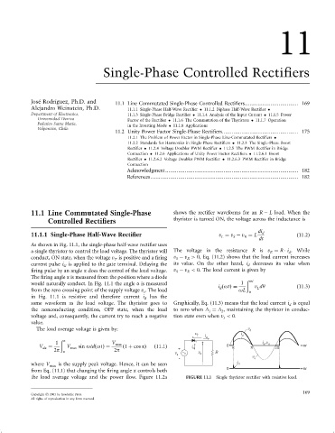
As shown in Fig. 11.1, the single-phase half-wave recti®er uses
a single thyristor to control the load voltage. The thyristor will The voltage in the resistance R is v ¼ R i . While
R
d
conduct, ON state, when the voltage v is positive and a ®ring v ÿ v > 0, Eq. (11.2) shows that the load current increases
S
R
T
current pulse i is applied to the gate terminal. Delaying the its value. On the other hand, i decreases its value when
d
G
®ring pulse by an angle a does the control of the load voltage. v ÿ v < 0. The load current is given by
S
R
The ®ring angle a is measured from the position where a diode
ð ot
would naturally conduct. In Fig. 11.1 the angle a is measured 1
i ðotÞ¼ v dy ð11:3Þ
L
d
from the zero crossing point of the supply voltage v . The load oL a
s
in Fig. 11.1 is resistive and therefore current i d has the
same waveform as the load voltage. The thyristor goes to Graphically, Eq. (11.3) means that the load current i is equal
d
the nonconducting condition, OFF state, when the load to zero when A ¼ A , maintaining the thyristor in conduc-
1 2
voltage and, consequently, the current try to reach a negative tion state even when v < 0.
s
value.
The load average voltage is given by: v d
v i
T i d
d
1 ð p V max + i ,v d
d
V da ¼ V max sin otdðotÞ¼ ð1 þ cos aÞ ð11:1Þ i 0 a p 2p wt
2p a 2p + G
v v d R
s v
- s
where V max is the supply peak voltage. Hence, it can be seen - i G
from Eq. (11.1) that changing the ®ring angle a controls both 0 wt
the load average voltage and the power ¯ow. Figure 11.2a FIGURE 11.1 Single thyristor recti®er with resistive load.
169
Copyright # 2001 by Academic Press.
All rights of reproduction in any form reserved.