
Page 206 - Rashid, Power Electronics Handbook
P. 206
12 Three-Phase Controlled Recti®ers 195
+ +
v D Firing angle:a
v L dead time
+ -
v D v D
-
- Firing angle:a = 180° - a +
v D
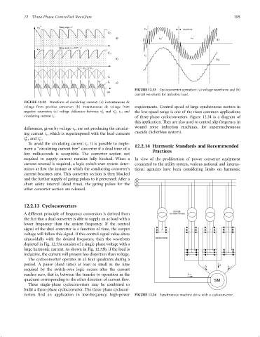
FIGURE 12.33 Cycloconverter operation: (a) voltage waveform; and (b)
w
current waveform for inductive load.
FIGURE 12.32 Waveform of circulating current: (a) instantaneous dc
voltage from positive converter; (b) instantaneous dc voltage from requirements. Control speed of large synchronous motors in
ÿ
negative converter; (c) voltage difference between n þ and n , n r , and
D D the low-speed range is one of the most common applications
circulating current i r . of three-phase cycloconverters. Figure 12.34 is a diagram of
this application. They are also used to control slip frequency in
differences, given by voltage n , are not producing the circulat- wound rotor induction machines, for supersynchronous
r
ing current i , which is superimposed with the load currents cascade (Scherbius system).
r
þ
ÿ
i , and i .
D D
To avoid the circulating current i , it is possible to imple- 12.2.14 Harmonic Standards and Recommended
r
ment a ‘‘circulating current free'' converter if a dead time of a Practices
few milliseconds is acceptable. The converter section not
required to supply current remains fully blocked. When a In view of the proliferation of power converter equipment
current reversal is required, a logic switch-over system deter- connected to the utility system, various national and interna-
mines at ®rst the instant at which the conducting converter's tional agencies have been considering limits on harmonic
current becomes zero. This converter section is then blocked
and the further supply of gating pulses to it prevented. After a
short safety interval (dead time), the gating pulses for the
other converter section are released.
12.2.13 Cycloconverters
POWER
A different principle of frequency conversion is derived from TRANSFORMERS
the fact that a dual converter is able to supply an ac load with a
lower frequency than the system frequency. If the control
signal of the dual converter is a function of time, the output
voltage will follow this signal. If this control signal value alters
sinusoidally with the desired frequency, then the waveform
depicted in Fig. 12.33a consists of a single-phase voltage with a
large harmonic current. As shown in Fig. 12.33b, if the load is
inductive, the current will present less distortion than voltage.
The cycloconverter operates in all four quadrants during a
period. A pause (dead time) at least as small as the time
required by the switch-over logic occurs after the current
reaches zero, that is, between the transfer to operation in the
quadrant corresponding to the other direction of current ¯ow.
Three single-phase cycloconverters may be combined to
build a three-phase cycloconverter. The three-phase cyclocon-
verters ®nd an application in low-frequency, high-power FIGURE 12.34 Synchronous machine drive with a cycloconverter.