Page 205 - Rashid, Power Electronics Handbook
P. 205

194                                                                                           J. W. Dixon

               the ac side 5th and 7th harmonic currents and dc side 6th  Substituting (Eq. 12.46) into (12.45):
               harmonic voltage, thus resulting in signi®cant savings in

               harmonic ®lters.                                                          cos a þ cosða þ mÞ
                                                                                 I ¼ I                           ð12:47Þ
                                                                                  P
                 Some useful relations for HVDC systems include:                                2
                 (a) recti®er side:
                                   p                             as I ¼ I cos j, it yields
                                                                       P
                      P ¼ V   I ¼    3   V  prim    I rms  cos j  ð12:40Þ
                       D    D   D        f ÿf  line

                                                                                         cos a þ cosða þ mÞ
                                                                                 cos j ¼                         ð12:48Þ
                                                                                                2
                                                                    (b) inverter side: The same equations are applied for the
                                                                    inverter side, but the ®ring angle a is replaced by g, where g
                                                                    is (see Fig. 12.30):
                                    I ¼ I cos j
                                    P

                                    I ¼ I sin j                                      g ¼ 180 ÿða þ m Þ           ð12:49Þ
                                                                                                I
                                                                                                    I
                                    Q
                                                                    As reactive power always goes in the converter direction, at the
                                p   prim
               ; P ¼ V   I ¼      3   V f ÿf    I P         ð12:41Þ  inverter side Eq. (12.44) becomes:
                             D
                    D
                         D
                                                                               p 
                         V   I D                                             a 2  3   V prim
                           D
                    I ¼ p   prim                         ð12:42Þ   I  ¼ÿ   I     f ÿf I  ‰sin 2ðg þ m Þÿ sin 2g ÿ 2m Šð12:50Þ
                    P
                          3   V                                        Q 1    4p   o L           I           I
                             f ÿf                                                  I I
                          p   prim
                        a 2  3   V f ÿf
                    I ¼            ‰cos 2a ÿ cos 2ða þ mފ  ð12:43Þ
                    P
                          4p   oL
                                S                                   12.2.12 Dual Converters
                          p 
                               prim
                        a 2  3   V f ÿf                             In many variable-speed drives, four-quadrant operation is
                    I ¼            ‰sin 2ða þ mÞÿ sin 2a ÿ 2mŠ  ð12:44Þ
                    Q                                               required, and three-phase dual converters are extensively
                          4p   oL S
                           p                                     used in applications up to the 2 MW level. Figure 12.31
                          a 6 cos a þ cosða þ mÞ                    shows a three-phase dual converter, where two converters
                    I ¼ I D                                 ð12:45Þ
                    P
                           p          2                             are connected back-to-back.
                                                                      In the dual converter, one recti®er provides the positive
               Fundamental secondary component of I:                current to the load, and the other the negative current. Due to
                                        p                        the instantaneous voltage differences between the output
                                       a 6                          voltages of the converters, a circulating current ¯ows through
                                    I ¼    I D              ð12:46Þ
                                         p                          the bridges. The circulating current is normally limited by
                                                                    circulating reactor L D  as shown in Fig. 12.31. The two
                                                                    converters are controlled in such a way that if a þ  is the
                          a
                                                                    delay angle of the positive current converter, the delay angle
                                                                                                             þ
                                                                                                  ÿ

                             m                                      of the negative current converter is a ¼ 180 ÿ a .
                                                                      Figure 12.32 shows the instantaneous dc voltages of each
                                                                    converter, n þ  and n . Despite the average voltage V is the
                                                                                    ÿ
                                                                              D     D                           D
                                                             w      same in both the converters, their instantaneous voltage
                                                                                    +  L D/2  L D/2
                                                                                   i D
                                                                       v A  i A         + v r -
                                                            w
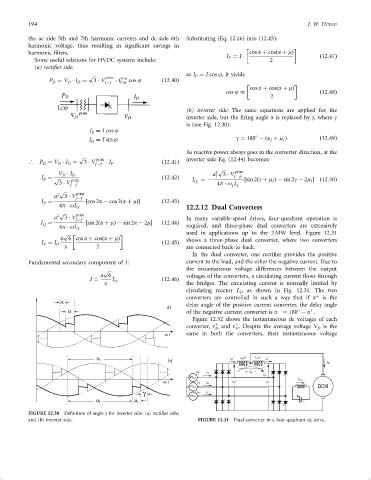
               FIGURE 12.30  De®nition of angle g for inverter side: (a) recti®er side;
               and (b) inverter side.                                   FIGURE 12.31  Dual converter in a four-quadrant dc drive.
   200   201   202   203   204   205   206   207   208   209   210