Page 74 - Rashid, Power Electronics Handbook
P. 74

4 Gate Turn-Off Thyristors                                                                           59


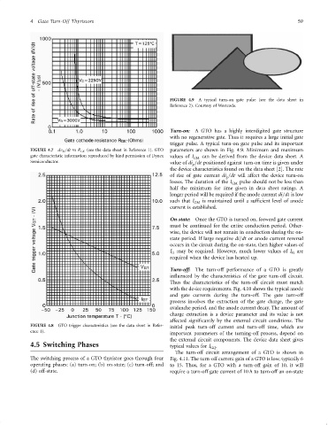
                                                                      FIGURE 4.9  A typical turn-on gate pulse (see the data sheet in
                                                                      Reference 2). Courtesy of Westcode.


                                                                      Turn-on:  A GTO has a highly interdigited gate structure
                                                                      with no regenerative gate. Thus it requires a large initial gate
                                                                      trigger pulse. A typical turn-on gate pulse and its important
                 FIGURE 4.7  dv D =dt vs R GK (see the data sheet in Reference 1). GTO  parameters are shown in Fig. 4.9. Minimum and maximum
                 gate characteristic information reproduced by kind permission of Dynex  values of I  can be derived from the device data sheet. A
                                                                               GM
                 Semiconductor.                                       value of di =dt positioned against turn-on time is given under
                                                                              g
                                                                      the device characteristics found on the data sheet [2]. The rate
                                                                      of rise of gate current di =dt will affect the device turn-on
                                                                                           g
                                                                      losses. The duration of the I  pulse should not be less than
                                                                                             GM
                                                                      half the minimum for time given in data sheet ratings. A
                                                                      longer period will be required if the anode current di=dt is low
                                                                      such that I GM  is maintained until a suf®cient level of anode
                                                                      current is established.
                                                                      On-state:  Once the GTO is turned on, forward gate current
                                                                      must be continued for the entire conduction period. Other-
                                                                      wise, the device will not remain in conduction during the on-
                                                                      state period. If large negative di=dt or anode current reversal
                                                                      occurs in the circuit during the on-state, then higher values of
                                                                      I may be required. However, much lower values of I are
                                                                                                                    G
                                                                       G
                                                                      required when the device has heated up.
                                                                      Turn-off:  The turn-off performance of a GTO is greatly
                                                                      in¯uenced by the characteristics of the gate turn-off circuit.
                                                                      Thus the characteristics of the turn-off circuit must match
                                                                      with the de-ice requirements. Fig. 4.10 shows the typical anode
                                                                      and gate currents during the turn-off. The gate turn-off
                                                                      process involves the extraction of the gate charge, the gate
                                                                      avalanche period, and the anode current decay. The amount of
                                                                      charge extraction is a device parameter and its value is not
                                                                      affected signi®cantly by the external circuit conditions. The
                 FIGURE 4.8  GTO trigger characteristics (see the data sheet in Refer-  initial peak turn-off current and turn-off time, which are
                 ence 1).
                                                                      important parameters of the turning-off process, depend on
                                                                      the external circuit components. The device data sheet gives
                 4.5 Switching Phases                                 typical values for I GQ .
                                                                        The turn-off circuit arrangement of a GTO is shown in
                 The switching process of a GTO thyristor goes through four  Fig. 4.11. The turn-off current gain of a GTO is low, typically 6
                 operating phases: (a) turn-on; (b) on-state; (c) turn-off; and  to 15. Thus, for a GTO with a turn-off gain of 10, it will
                 (d) off-state.                                       require a turn-off gate current of 10 A to turn-off an on-state
   69   70   71   72   73   74   75   76   77   78   79