
Page 71 - Rashid, Power Electronics Handbook
P. 71
56 M. H. Rashid
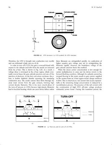
FIGURE 4.1 GTO structure: (a) GTO symbol; (b) GTO structure.
Therefore, the GTO is brought into conduction very rapidly these ®laments are extinguished quickly. An application of
and can withstand a high turn-on di=dt. higher negative gate voltage may aid in extinguishing the
In order to turn off a GTO, the gate is reversed-biased with ®laments rapidly. However, the breakdown voltage of the
respect to the cathode and holes from the anode are extracted gate-cathode junction limits this method.
from the p-base. This is shown in Fig. 4.2b. As a result, a When the excess carrier concentration is low enough for
voltage drop is developed in the p-base region, which even- carrier multiplication to cease and the device reverts to the
tually reverse biases the gate cathode junction and cuts off the forward blocking condition. Although the cathode current has
injection of electrons. As the hole extraction continues, the p- stopped ¯owing at this point, anode-to-gate current supplied
base is further depleted, thereby squeezing the remaining by the carriers from an n-base region-stored charge continues
conduction area. The anode current then ¯ows through the to ¯ow. This is observed as a tail current that decays exponen-
areas most remote from the gate contacts, forming high tially as the remaining charge concentration is reduced by a
current density ®laments. This is the most crucial phase of recombination process. The presence of this tail current with
the turn-off process in GTOs because high-density ®laments the combination of high GTO off-state voltage produces
lead to localized heating, which can cause device failure unless substantial power losses. During this transition period, the
(a) (b)
FIGURE 4.2 (a) Turn-on; and (b) turn-off of GTOs.