
Page 66 - Rashid, Power Electronics Handbook
P. 66
3 Thyristors 51
FIGURE 3.34 Parallel connection of two 6-pulse converters for high-current applications.
D-Y and Y-Y transformers in order to obtain a 12-pulse An electronic controller controls the gate current of these
converter and a reduced output ripple. The ®lters are required thyristors. The recti®er and inverter sections can be thyristor
to reduce the current harmonic generated by the converter. circuits. A controlled recti®er is used in conjunction with a
Thyristors are required in order to reduce the voltage ampli- square wave or pulse-width modulated (PWM) voltage source
tude to the ac voltage amplitude level by appropriate switching inverter (VSI) to create the speed-torque controller system.
action. Figure 3.36 shows a square-wave or PWM VSI with a
When a large amount of current and relatively low voltage is controlled recti®er on the input side. The switch block inverter
required, it is possible to connect, using a specially designed is made of thyristors (usually GTOs) for high power. Low-
inductor, two 6-pulse line-frequency converters connected power motor controllers often use IGBT inverters.
through D-Y and Y-Y transformers. This topology is shown In motor control, thyristors are also used in current-source
in Fig. 3.34. inverter (CSI) topologies. When the motor is controlled by a
CSI, a controlled recti®er is also needed on the input side.
Figure 3.37 shows a typical CSI inverter.
Diodes, capacitors, and the motor leakage inductance make
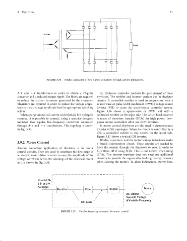
3.9.2 Motor Control
a forced commutation circuit. These circuits are needed to
Another important application of thyristors is in motor force the current through the thyristors to zero, in order to
control circuits. They are used to construct the ®rst stage of turn them off if using SCRs. This is not needed when using
an electric motor drive in order to vary the amplitude of the GTOs. This inverter topology does not need any additional
voltage waveform across the windings of the electrical motor circuitry to provide the regenerative braking (energy recovery
as it is shown in Fig. 3.35. when slowing the motor). To allow bidirectional power ¯ow,
FIGURE 3.35 Variable frequency converter for motor control.