
Page 67 - Rashid, Power Electronics Handbook
P. 67
J. Hudgins et al.
5252 J. Hudgins et al.
FIGURE 3.36 Pulsewidth modulated or square-wave inverter with a controlled recti®er input.
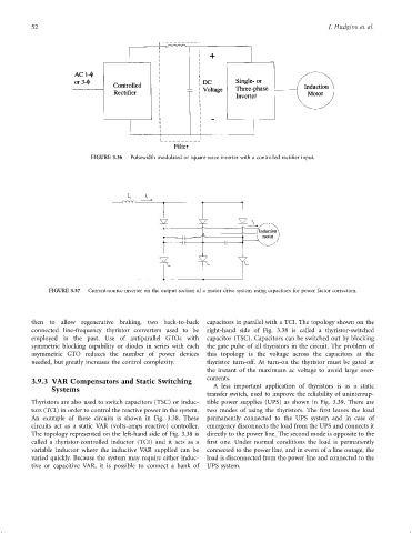
FIGURE 3.37 Current-source inverter on the output section of a motor drive system using capacitors for power factor correction.
then to allow regenerative braking, two back-to-back capacitors in parallel with a TCI. The topology shown on the
connected line-frequency thyristor converters used to be right-hand side of Fig. 3.38 is called a thyristor-switched
employed in the past. Use of antiparallel GTOs with capacitor (TSC). Capacitors can be switched out by blocking
symmetric blocking capability or diodes in series with each the gate pulse of all thyristors in the circuit. The problem of
asymmetric GTO reduces the number of power devices this topology is the voltage across the capacitors at the
needed, but greatly increases the control complexity. thyristor turn-off. At turn-on the thyristor must be gated at
the instant of the maximum ac voltage to avoid large over-
currents.
3.9.3 VAR Compensators and Static Switching
Systems A less important application of thyristors is as a static
transfer switch, used to improve the reliability of uninterrup-
Thyristors are also used to switch capacitors (TSC) or induc- tible power supplies (UPS) as shown in Fig. 3.39. There are
tors (TCI) in order to control the reactive power in the system. two modes of using the thyristors. The ®rst leaves the load
An example of these circuits is shown in Fig. 3.38. These permanently connected to the UPS system and in case of
circuits act as a static VAR (volts-amps reactive) controller. emergency disconnects the load from the UPS and connects it
The topology represented on the left-hand side of Fig. 3.38 is directly to the power line. The second mode is opposite to the
called a thyristor-controlled inductor (TCI) and it acts as a ®rst one. Under normal conditions the load is permanently
variable inductor where the inductive VAR supplied can be connected to the power line, and in event of a line outage, the
varied quickly. Because the system may require either induc- load is disconnected from the power line and connected to the
tive or capacitive VAR, it is possible to connect a bank of UPS system.