
Page 65 - Rashid, Power Electronics Handbook
P. 65
J. Hudgins et al.
5050 J. Hudgins et al.
a trade-off between accuracy and complexity. An example
of the values of the RC delay network, R 's, R 's, M's is
KC
GC
given in Table 3.6.
3.9 Applications
The most important application of thyristors is for line-
frequency, phase-controlled recti®ers. This family includes
several topologies, of which one of the most important is
used to construct high voltage dc (HVDC) transmission
systems. A single-phase controlled recti®er is shown in Fig.
3.31.
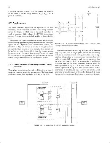
The presence of thyristors makes the average output voltage
controllable by appropriate gating of the thyristors. If the gate FIGURE 3.32 A 3-phase controlled bridge circuit used as a basic
signals to the thyristors were continuously applied, the
topology for many converter systems.
thyristors in Fig. 3.31 behave as diodes. If no gate currents
are supplied they behave as open circuits. Gate current can
be applied any time (phase delay) after the forward voltage The thyristors in the circuit of Fig. 3.32 are used in the same
becomes positive. Using this phase-control feature it is possi- way they were used in single-phase circuits but necessarily
ble to produce an average output voltage less than the average with more complex control. Starting from this basic con®g-
output voltage obtained from an uncontrolled recti®er. uration, it is possible to construct more complex circuits in
order to obtain high-voltage or high-current outputs, or just
to reduce the output ripple by constructing a multiphase
converter. One of the most important systems using the
3.9.1 Direct current-Alternating current Utility
Inverters topology shown in Fig. 3.32 as a basic circuit is the HVDC
system represented in Fig. 3.33. This system is made by two
Three-phase converters can be made in different ways, accord- converters, a transmission line, and two ac systems. Each
ing to the system in which they are employed. The basic circuit converter terminal is made of two poles. Each pole is made
used to construct these topologies is shown in Fig. 3.32. by connecting two 6-pulse line-frequency converters through
FIGURE 3.33 A high-voltage dc (HVDC) transmission system.