
Page 61 - Rashid, Power Electronics Handbook
P. 61
J. Hudgins et al.
4646 J. Hudgins et al.
FIGURE 3.25 Gate i-n curve for a typical thyristor.
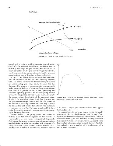
enough and, in order to avoid an unwanted turn-off imme- i G (t)
diately after the turn-on, it should last for a suf®cient time. In
estimating how large the gate current pulse should be to
ensure device turn on, the gate current-voltage characteristic,
which is given with the device data sheet, must be used. An
example of this kind of data sheet is shown in Fig. 3.25.
In Fig. 3.25 are shown the gate current-voltage character-
istics for the maximum and minimum operating tempera-
tures. The dashed line represents the minimum gate current
and corresponding gate voltage needed to ensure that the
thyristor will be triggered at various operating temperatures. It
is also known as the locus of minimum ®ring points. On the
data sheet it is possible to ®nd a line representing the
maximum operating power of the thyristor gating internal t
circuit. The straight line, between V and V =R , represents 0
G
G
G
the current voltage characteristic of the equivalent trigger FIGURE 3.26 Gate current waveform showing large initial current
circuit. If the equivalent trigger circuit line intercepts the followed by a suitable back-porch value.
two gate current-voltage characteristics for the maximum
and minimum operating temperatures after they intercept
the dashed line and before they intercept the maximum
operating power line, then the trigger circuit is able to turn of the device. A shaped gate current waveform of this type is
on the thyristor at any operating temperature without destroy- shown in Fig. 3.26.
ing or damaging the device. In order to keep the power and control circuits electrically
Another feature of the gating process that should be unconnected, the gate signal generator and the gate of the
analyzed is the fast turn-on required for these devices. In thyristor are often connected through a transformer. There is a
order to allow a fast turn-on, and correspondingly large anode transformer winding for each thyristor; this way, unwanted
di=dt during the turn-on process, a large gate current pulse is short-circuits between devices are avoided. A general block
supplied during the initial turn-on phase with a large di =dt. diagram of a thyristor gate-trigger circuit is shown in Fig. 3.27.
G
The gate current is kept on, at lower value, for some time after This application is for a standard bridge con®guration often
the thyristor is turned on in order to avoid unwanted turn-off used in power converters.