
Page 62 - Rashid, Power Electronics Handbook
P. 62
3 Thyristors 47
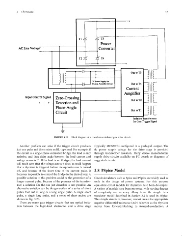
FIGURE 3.27 Block diagram of a transformer-isolated gate drive circuit.
Another problem can arise if the trigger circuit produces (typically MOSFETs) con®gured in a push-pull output. The
just one pulse and there exists an RL-type load. For example, if dc power supply voltage for the drive stage is provided
the circuit is a single-phase controlled bridge, the load is only through transformer isolation. Many device manufacturers
resistive, and then delay angle between the load current and supply drive circuits available on PC boards or diagrams of
voltage across is 0 . If the load is an RL-type, the load current suggested circuits.
will reach zero after the voltage across it does. It could happen
that a thyristor is triggered before the opposite one is turned
off, and because of the short time of the current pulse, it 3.8 PSpice Model
becomes impossible to control the bridge in the desired way. A
possible solution to this problem could be the generation of a Circuit simulators such as Spice and PSpice are widely used as
longer current pulse. Because of the presence of the transfor- tools in the design of power systems. For this purpose
mer, a solution like the one just described is not possible. An equivalent circuit models for thyristors have been developed.
alternative solution can be the generation of a series of short A variety of models have been proposed with varying degrees
pulses that last as long as a long single pulse. A single short of complexity and accuracy. Many times the simple two-
pulse, a single long pulse, and a series of short pulses are transistor model described in Section 3.2 is used in PSpice.
shown in Fig. 3.28. This simple structure, however, cannot create the appropriate
There are many gate trigger circuits that use optical isola- negative-differential-resistance (ndr) behavior as the thyristor
tion between the logic-level electronics and a drive stage moves from forward-blocking to forward-conduction. A