Page 59 - Rashid, Power Electronics Handbook
P. 59

J. Hudgins et al.
               4444                                                                                      J.  Hudgins  et  al.
                                      cathode                       3.6.4 Optically Triggered Thyristors
                                                                    Optically gated thyristors have traditionally been used in
                                                                    power utility applications where series stacks of devices are
                                       n +                          necessary to achieve the high voltages required. Isolation
                                                                    between gate drive circuits for circuits such as static VAR
                                                                    compensators and high-voltage dc to ac inverters have driven
                                   b uried gate (p ) +
                                                                    the development of this class of devices. One of the most
                                                                    recent devices can block 6 kV forward and reverse, conduct
                                        n -                         2.5 kA average current, and maintains a di=dt capability of 300
                                                                    A=ms, and a dn=dt capability of 3000 V=ms, with a required
                                                                    trigger power of 10 mW. An integrated light-triggered and
                                                                    light-quenched static induction thyristor has been produced
                                                                    that can block 1.2 kV and conduct up to 20 A (at a forward
                                                                    drop of 2.5 V). This device is an integration of a normally off,
                                                                    buried-gate static induction photothyristor and a normally off,
                                                                    p-channel Darlington surface-gate static induction photo-
                                        n +                         transistor. The optical trigger and quenching power required
                                                                    is <5 and 0.2 mW, respectively.
                                        p +

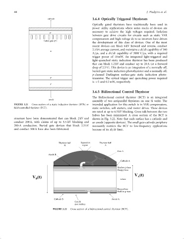
                                                                    3.6.5 Bidirectional Control Thyristor

                                                                    The Bidirectional control thyristor (BCT) is an integrated
                                       anode
                                                                    assembly of two antiparallel thyristors on one Si wafer. The
               FIGURE 3.21  Cross section of a static induction thyristor (SITh) or  intended application for this switch is in VAR compensators,
               ®eld-controlled thyristor (FCT).                     static switches, soft starters, and motor drives. These devices
                                                                    are rated at up to 6.5 kV blocking. Cross talk between the two
                                                                    halves has been minimized. A cross section of the BCT is
               structure have been demonstrated that can block 2 kV and  shown in Fig. 3.22. Note that each surface has a cathode and
               conduct 200 A, with claims of up to 3.5-kV blocking and  an anode (opposite devices). The small gate-cathode periphery
               200-A conduction. Buried gate devices that block 2.5 kV  necessarily restricts the BCT to low-frequency applications
               and conduct 300 A have also been fabricated.         because of its di=dt limit.


                                             Thyristor half  Separation  Thyristor half
                                                 B           region         A

                                                                                     Gate A
                                       Anode B

                                                                                       Cathode A

                                                                                     Shallow p-b ase
                                                                                     Deep p-b ase
                            V (t)                                                      n-b ase  V (t)
                                                                                                  A
                              B


                                                                                     Deep p-b ase
                                                                                     Shallow p-b ase

                                          Cathode B                              Anode A
                                                        Gate B
                                                        (not visib le)
                                         FIGURE 3.22  Cross section of a bidirectional control thyristor (BCT).
   54   55   56   57   58   59   60   61   62   63   64