
Page 85 - Rashid, Power Electronics Handbook
P. 85
5 Power Bipolar Transistors 71
grated circuits emphasis. A circuit must be speci®ed in terms
of element names, element values, nodes, variable parameters,
R and sources. Several types of circuit analysis are possible using
D 1
SPICE:
T P
D nonlinear dc analysis Ð calculates dc transference;
nonlinear transient analysis Ð calculates signals as a
function of time;
C linear ac analysis Ð computes a Bode plot of output as a
function of frequency;
noise analysis;
sensitivity analysis;
distortion analysis;
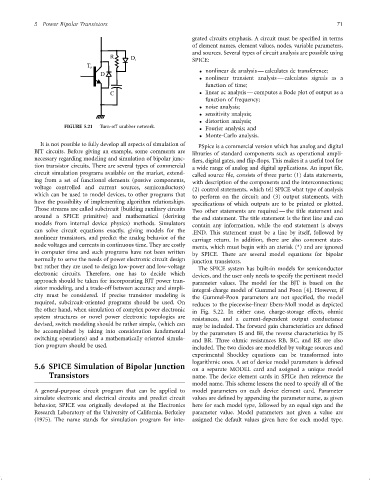
FIGURE 5.21 Turn-off snubber network. Fourier analysis; and
Monte-Carlo analysis.
It is not possible to fully develop all aspects of simulation of PSpice is a commercial version which has analog and digital
BJT circuits. Before giving an example, some comments are libraries of standard components such as operational ampli-
necessary regarding modeling and simulation of bipolar junc- ®ers, digital gates, and ¯ip-¯ops. This makes it a useful tool for
tion transistor circuits. There are several types of commercial a wide range of analog and digital applications. An input ®le,
circuit simulation programs available on the market, extend- called source ®le, consists of three parts: (1) data statements,
ing from a set of functional elements (passive components, with description of the components and the interconnections;
voltage controlled and current sources, semiconductors)
(2) control statements, which tell SPICE what type of analysis
which can be used to model devices, to other programs that
to perform on the circuit; and (3) output statements, with
have the possibility of implementing algorithm relationships.
speci®cations of which outputs are to be printed or plotted.
Those streams are called subcircuit (building auxiliary circuits
Two other statements are required Ð the title statement and
around a SPICE primitive) and mathematical (deriving
the end statement. The title statement is the ®rst line and can
models from internal device physics) methods. Simulators
contain any information, while the end statement is always
can solve circuit equations exactly, giving models for the
.END. This statement must be a line by itself, followed by
nonlinear transistors, and predict the analog behavior of the
carriage return. In addition, there are also comment state-
node voltages and currents in continuous time. They are costly
ments, which must begin with an aterisk (*) and are ignored
in computer time and such programs have not been written by SPICE. There are several model equations for bipolar
normally to serve the needs of power electronic circuit design junction transistors.
but rather they are used to design low-power and low-voltage The SPICE system has built-in models for semiconductor
electronic circuits. Therefore, one has to decide which devices, and the user only needs to specify the pertinent model
approach should be taken for incorporating BJT power tran- parameter values. The model for the BJT is based on the
sistor modeling, and a trade-off between accuracy and simpli- integral-charge model of Gummel and Poon [4]. However, if
city must be considered. If precise transistor modeling is the Gummel-Poon parameters are not speci®ed, the model
required, subcircuit-oriented programs should be used. On reduces to the piecewise-linear Ebers-Moll model as depicted
the other hand, when simulation of complex power electronic in Fig. 5.22. In either case, charge-storage effects, ohmic
system structures or novel power electronic topologies are resistances, and a current-dependent output conductance
devised, switch modeling should be rather simple, (which can may be included. The forward gain characteristics are de®ned
be accomplished by taking into consideration fundamental by the parameters IS and BF, the reverse characteristics by IS
switching operations) and a mathematically oriented simula- and BR. Three ohmic resistances RB, RC, and RE are also
tion program should be used. included. The two diodes are modelled by voltage sources and
experimental Shockley equations can be transformed into
logarithmic ones. A set of device model parameters is de®ned
5.6 SPICE Simulation of Bipolar Junction on a separate MODEL card and assigned a unique model
Transistors name. The device element cards in SPICe then reference the
model name. This scheme lessens the need to specify all of the
A general-purpose circuit program that can be applied to model parameters on each device element card. Parameter
simulate electronic and electrical circuits and predict circuit values are de®ned by appending the parameter name, as given
behavior, SPICE was originally developed at the Electronics here for each model type, followed by an equal sign and the
Research Laboratory of the University of California, Berkeley parameter value. Model parameters not given a value are
(1975). The name stands for simulation program for inte- assigned the default values given here for each model type.