
Page 84 - Rashid, Power Electronics Handbook
P. 84
M. Godoy Simo˜es
70
70 M. Godoy Simo ˜e s
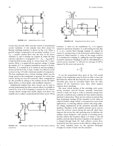
+V cc
T R1 T P N 1 N 2
+
vs
R 1
R 1 C 1
D 1
R 2
T 1 T P
T 1 Z 1
D 1 C 1 R 2
N 3 N 4
FIGURE 5.18 Isolated base drive circuit.
FIGURE 5.20 Proportional base drive circuit.
circuits may provide either constant current or proportional
transistor T turns on, the transformer T R1 is in negative
1
current excitation. A very popular base drive circuit for
saturation and power transistor T is off. During the time that
P
¯oating switching transistor is shown in Fig. 5.18. When a
T is on a current ¯ows through winding N , limited by
1
1
positive voltage is impressed on the secondary winding (V )of resistor R , storing energy in the transformer and holding it at
S
1
T , a positive current ¯ows into the base of the power saturation. When transistor T turns off, the energy stored in
R1
transistor T and it switches on (resistor R limits the base 1
P 1 N is transferred to winding N , pulling the core from negative
current). Capacitor C is charged by (V ÿ V ÿ V Þ and T 1 4
1 S D1 BE 1 to positive saturation. Windings N and N will withstand as a
is kept blocked because diode D reverse biases the T base- 2 4
1 1 current source, transistor T will stay on, and gain b will be
emitter. When V is zipped off, the capacitor voltage V brings P
S C imposed by the turns ratio given by:
the emitter of T to a negative potential in respect to its base.
1
Therefore, T is excited so as to switch on and start pulling a
1 N 4
reverse current from the T base. Another very effective circuit b ¼ ð5:7Þ
P N
is shown in Fig. 5.19 with a minimum number of components. 2
The base transformer has a tertiary winding, which uses the
To use the proportional drive given in Fig. 5.20 careful
energy stored in the transformer to generate the reverse base design of the transformer must be done in order to have the
current during the turn-off command. Other con®gurations ¯ux balanced, which will then keep the core under saturation.
are also possible by adding to the isolated circuits the Baker
Transistor gain must be somewhat higher than the value
clamp diodes, or Zener diodes with paralleled capacitors.
imposed by the transformer turns ratio, which requires
Sophisticated isolated base drive circuits can be used to
cautious device matching.
provide proportional base drive currents where it is possible to
The most critical portion of the switching cycle occurs
control the value of b; by keeping it constant for all collector
during transistor turn-off because normally reverse-base
currents shorter storage time results. Figure 5.20 shows one
current is made very large in order to minimize storage time
possible way to realize a proportional base drive circuit. When
and such a condition may avalanche the base-emitter junction
and lead to destruction. There are two options to prevent this
from happening: turning off the transistor at low values of
collector-emitter voltage (which is not practical in most of the
R 1
T P
applications), or reducing collector current with rising collec-
tor voltage, implemented by RC protective networks called
R 2
snubbers. Therefore, an RC snubber network can be used to
divert the collector current during the turn-off, which then
improves the reverse bias safe operating area; in addition, the
D 1 snubber circuit dissipates a fair amount of switching power
T 1
and this relieves the transistor. Figure 5.21 shows a turn-off
snubber network; when the power transistor is off capacitor C
is charged through diode D1. Such collector current ¯ows
temporarily into the capacitor as the collector-voltage rises; as
FIGURE 5.19 Transformer coupled base drive with tertiary winding the power transistor turns on, the capacitor discharges
transformer. through the resistor R back into the transistor.