
Page 88 - Rashid, Power Electronics Handbook
P. 88
M. Godoy Simo˜es
74
74 M. Godoy Simo ˜e s
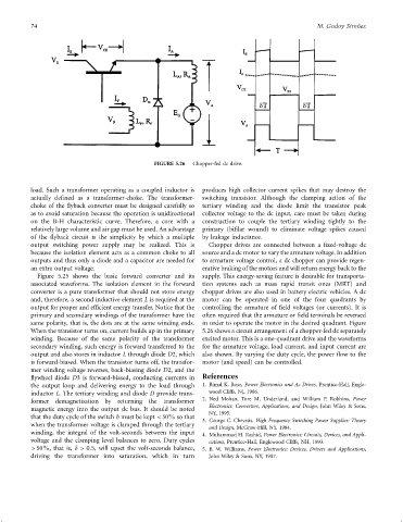
FIGURE 5.26 Chopper-fed dc drive.
load. Such a transformer operating as a coupled inductor is produces high collector current spikes that may destroy the
actually de®ned as a transformer-choke. The transformer- switching transistor. Although the clamping action of the
choke of the ¯yback converter must be designed carefully so tertiary winding and the diode limit the transistor peak
as to avoid saturation because the operation is unidirectional collector voltage to the dc input, care must be taken during
on the B-H characteristic curve. Therefore, a core with a construction to couple the tertiary winding tightly to the
relatively large volume and air gap must be used. An advantage primary (bi®lar wound) to eliminate voltage spikes caused
of the ¯yback circuit is the simplicity by which a multiple by leakage inductance.
output switching power supply may be realized. This is Chopper drives are connected between a ®xed-voltage dc
because the isolation element acts as a common choke to all source and a dc motor to vary the armature voltage. In addition
outputs and thus only a diode and a capacitor are needed for to armature voltage control, a dc chopper can provide regen-
an extra output voltage. erative braking of the motors and will return energy back to the
Figure 5.25 shows the basic forward converter and its supply. This energy-saving feature is desirable for transporta-
associated waveforms. The isolation element in the forward tion systems such as mass rapid transit ones (MRT) and
converter is a pure transformer that should not store energy chopper drives are also used in battery electric vehicles. A dc
and, therefore, a second inductive element L is required at the motor can be operated in one of the four quadrants by
output for proper and ef®cient energy transfer. Notice that the controlling the armature of ®eld voltages (or currents). It is
primary and secondary windings of the transformer have the often required that the armature or ®eld terminals be reversed
same polarity, that is, the dots are at the same winding ends. in order to operate the motor in the desired quadrant. Figure
When the transistor turns on, current builds up in the primary 5.26 shows a circuit arrangement of a chopper-fed dc separately
winding. Because of the same polarity of the transformer excited motor. This is a one-quadrant drive and the waveforms
secondary winding, such energy is forward transferred to the for the armature voltage, load current, and input current are
output and also stores in inductor L through diode D2, which also shown. By varying the duty cycle, the power ¯ow to the
is forward-biased. When the transistor turns off, the transfor- motor (and speed) can be controlled.
mer winding voltage reverses, back-biasing diode D2, and the
¯ywheel diode D3 is forward-biased, conducting currents in References
the output loop and delivering energy to the load through 1. Bimal K. Bose, Power Electronics and Ac Drives, Prentice-Hall, Engle-
inductor L. The tertiary winding and diode D provide trans- wood Cliffs, NJ, 1986.
former demagnetisation by returning the transformer 2. Ned Mohan, Tore M. Underland, and William P. Robbins, Power
Electronics: Converters, Applications, and Design, John Wiley & Sons,
magnetic energy into the output dc bus. It should be noted
NY, 1995.
that the duty cycle of the switch b must be kept <50% so that
3. George C. Chryssis, High Frequency Switching Power Supplies: Theory
when the transformer voltage is clamped through the tertiary
and Design, McGraw-Hill, NY, 1984.
winding, the integral of the volt-seconds between the input 4. Muhammad H. Rashid, Power Electronics: Circuits, Devices, and Appli-
voltage and the clamping level balances to zero. Duty cycles cations, Prentice-Hall, Englewood Cliffs, NH, 1993.
>50%, that is, d > 0:5, will upset the volt-seconds balance, 5. B. W. Williams, Power Electronics: Devices, Drivers and Applications,
driving the transformer into saturation, which in turn John Wiley & Sons, NY, 1987.