
Page 247 - Renewable Energy Devices and System with Simulations in MATLAB and ANSYS
P. 247
234 Renewable Energy Devices and Systems with Simulations in MATLAB and ANSYS ®
®
TABLE 9.4
Optimized Design of an 8 MW, 3600 V, 1500 rpm, and 480 rpm Permanent Magnet
Synchronous Generator (Price of Permanent Magnet: 150 USD/kg)
Total Total Stack PM
Weight Initial Cost Outer Stator Length Frequency Number Weight
Generator Efficiency (kg) (USD) Diameter (m) (m) (Hz) of Poles (kg)
8 MW, 0.98296 8560 197,027 1.252 3.5 75 6 629
1500 rpm
8 MW, 0.98475 9799 249,376 2.177 3 56 14 875
480 rpm
v wind MPPT T* e 2 i* q V* d V*
ω r calculation 3p ψ – Pl+SM a Machine- jω ψ R i
r PM
1 PM
i q ω ψ V b * side s s
r PM
dq/abc power V s
*=0 *
i d V q V c * converter ψ PM
– Pl+SM
i d –ω L i* θ er ji = i s
r q q
q
(a) (Rotor position) (b)
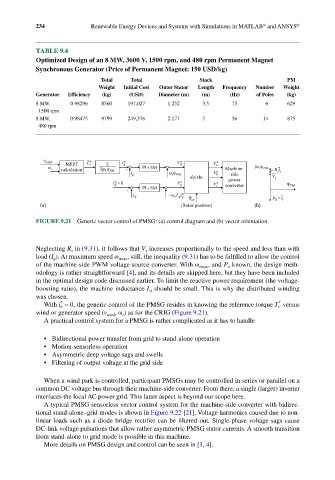
FIGURE 9.21 Generic vector control of PMSG: (a) control diagram and (b) vector orientation.
Neglecting R in (9.31), it follows that V increases proportionally to the speed and less than with
s
s
load (I ). At maximum speed ω rmax , still, the inequality (9.31) has to be fulfilled to allow the control
q
of the machine-side PWM voltage source converter. With ω rmax , and P known, the design meth-
n
odology is rather straightforward [4], and its details are skipped here, but they have been included
in the optimal design code discussed earlier. To limit the reactive power requirement (the voltage-
boosting ratio), the machine inductance L should be small. This is why the distributed winding
s
was chosen.
*
*
With i d = 0, the generic control of the PMSG resides in knowing the reference torque T e versus
wind or generator speed (v wind , ω ) as for the CRIG (Figure 9.21).
r
A practical control system for a PMSG is rather complicated as it has to handle
• Bidirectional power transfer from grid to stand-alone operation
• Motion-sensorless operation
• Asymmetric deep voltage sags and swells
• Filtering of output voltage at the grid side
When a wind park is controlled, participant PMSGs may be controlled in series or parallel on a
common DC voltage bus through their machine-side converter. From there, a single (larger) inverter
interfaces the local AC power grid. This latter aspect is beyond our scope here.
A typical PMSG sensorless vector control system for the machine-side converter with bidirec-
tional stand-alone–grid modes is shown in Figure 9.22 [21]. Voltage harmonics caused due to non-
linear loads such as a diode bridge rectifier can be filtered out. Single-phase voltage sags cause
DC-link voltage pulsations that allow rather asymmetric PMSG stator currents. A smooth transition
from stand-alone to grid mode is possible in this machine.
More details on PMSG design and control can be seen in [1, 4].