Page 249 - Renewable Energy Devices and System with Simulations in MATLAB and ANSYS
P. 249

236             Renewable Energy Devices and Systems with Simulations in MATLAB  and ANSYS ®
                                                                                ®

            9.5  DCE-SG
            So far, DCE-SGs have been applied in large wind energy conversion units mainly as direct-driven
            generators. However, their usage in 1G or 3(4)G transmission drives may also show merits such as
              •  Elimination of PMs (or reduction of PM weight/kW by hybrid excitation [8])
              •  Opportunity to use only a diode rectifier in the machine side, where the DC overexcitation
                 current controller alone provides the power flow to a common DC voltage bus of a wind park
              Although the superconducting SC–SGs have been proposed for up to 10 MW (direct driven) [8],
            they may be more suitable for 1G transmission drives in order to allow a reasonable frequency in the
            generator and the power converter. Superconducting SC–SCGs have been built with iron-back core
            (operating frequency 2.2 Hz) and with air-back core (operating frequency 0.833 Hz), giving an effi-
            ciency of 96.4%. The SC–SG does not allow any no-load voltage control. It may thus be controlled
            as a PMSG with very low internal inductance.
              In what follows, we will treat, in short, the DCE-SG:
              •  The phase circuit model for steady state
              •  Optimal design for unity power factor for 8 MW, 3.6 kV generator
              •  The dq model for transient simulation and analysis
              •  Vector control of the machine-side converter

              The steady-state phase circuit model of a DCE-SG is rather standard:

                                 *
                                 iR s + V s = − jωψ s ; ψ s  =  Li + Li +  Li         (9.31)
                                             r
                                                        dm F
                                                                    q q
                                 s
                                                               d d
                                         d (
                                      pL i F +( L d − ) ) ,,
                                                      d
                                                   q
                                 T e = 3 1        Li i q
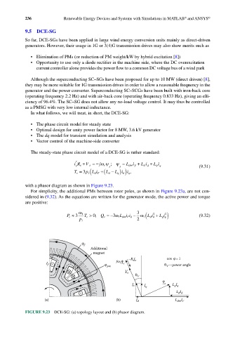
            with a phasor diagram as shown in Figure 9.23.
              For simplicity, the additional PMs between rotor poles, as shown in Figure 9.23a, are not con-
            sidered in (9.32). As the equations are written for the generator mode, the active power and torque
            are positive:
                                    1 ω                     3
                                                                 d (
                                                                        2
                                                                   2
                              P e ≈ 3  T e > 0;  Q e =−3ω 1 L ii d − ω 1  Li d + Li q)  (9.32)
                                                     dmF
                                                                      q
                                    1 p                     2
                                     f
                                        Additional
                                         magnet
                      N                                 –R I            cos    =1
                                                   jω ψ   s s
                     I f                            1  s
                                               pm                      θ V —power angle
                                                      V s
                                 NS
                                                           θ V
                                                                       ψ
                                                          I s  I q      s  L q I q
                                                                            L I
                                                                             d d
                                                                               I
                    (a)               S            (b)     I d              L dm F
            FIGURE 9.23  DCE-SG: (a) topology layout and (b) phasor diagram.
   244   245   246   247   248   249   250   251   252   253   254