
Page 260 - Renewable Energy Devices and System with Simulations in MATLAB and ANSYS
P. 260
Electric Generators and their Control for Large Wind Turbines 247
(a) (b) (c)
®
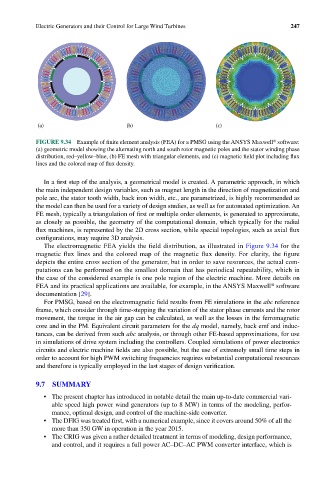
FIGURE 9.34 Example of finite element analysis (FEA) for a PMSG using the ANSYS Maxwell software:
(a) geometric model showing the alternating north and south rotor magnetic poles and the stator winding phase
distribution, red–yellow–blue, (b) FE mesh with triangular elements, and (c) magnetic field plot including flux
lines and the colored map of flux density.
In a first step of the analysis, a geometrical model is created. A parametric approach, in which
the main independent design variables, such as magnet length in the direction of magnetization and
pole arc, the stator tooth width, back iron width, etc., are parametrized, is highly recommended as
the model can then be used for a variety of design studies, as well as for automated optimization. An
FE mesh, typically a triangulation of first or multiple order elements, is generated to approximate,
as closely as possible, the geometry of the computational domain, which typically for the radial
flux machines, is represented by the 2D cross section, while special topologies, such as axial flux
configurations, may require 3D analysis.
The electromagnetic FEA yields the field distribution, as illustrated in Figure 9.34 for the
magnetic flux lines and the colored map of the magnetic flux density. For clarity, the figure
depicts the entire cross section of the generator, but in order to save resources, the actual com-
putations can be performed on the smallest domain that has periodical repeatability, which in
the case of the considered example is one pole region of the electric machine. More details on
FEA and its practical applications are available, for example, in the ANSYS Maxwell software
®
documentation [29].
For PMSG, based on the electromagnetic field results from FE simulations in the abc reference
frame, which consider through time-stepping the variation of the stator phase currents and the rotor
movement, the torque in the air gap can be calculated, as well as the losses in the ferromagnetic
core and in the PM. Equivalent circuit parameters for the dq model, namely, back emf and induc-
tances, can be derived from such abc analysis, or through other FE-based approximations, for use
in simulations of drive system including the controllers. Coupled simulations of power electronics
circuits and electric machine fields are also possible, but the use of extremely small time steps in
order to account for high PWM switching frequencies requires substantial computational resources
and therefore is typically employed in the last stages of design verification.
9.7 SUMMARY
• The present chapter has introduced in notable detail the main up-to-date commercial vari-
able speed high power wind generators (up to 8 MW) in terms of the modeling, perfor-
mance, optimal design, and control of the machine-side converter.
• The DFIG was treated first, with a numerical example, since it covers around 50% of all the
more than 350 GW in operation in the year 2015.
• The CRIG was given a rather detailed treatment in terms of modeling, design performance,
and control, and it requires a full power AC–DC–AC PWM converter interface, which is