
Page 255 - Renewable Energy Devices and System with Simulations in MATLAB and ANSYS
P. 255
242 Renewable Energy Devices and Systems with Simulations in MATLAB and ANSYS ®
®
Electric efficiency
0.94
0.92
0.9
0.88
Efficiency 0.86
0.84
0.82
R
0.8 0.8 RL
0.6 RL
0.78 0.8 RC
0.6 RC
0.76
0 0.2 0.4 0.6 0.8 1 1.2
Load current (pu)
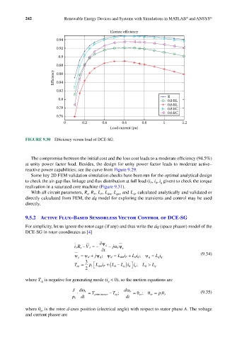
FIGURE 9.30 Efficiency versus load of DCE-SG.
The compromise between the initial cost and the loss cost leads to a moderate efficiency (94.5%)
at unity power factor load. Besides, the design for unity power factor leads to moderate active–
reactive power capabilities; see the curve from Figure 9.29.
Some key 2D FEM validation simulation checks have been run for the optimal analytical design
to check the air-gap flux linkage and flux distribution at full load (i , i , i given) to check the torque
F
d
q
realization in a saturated core machine (Figure 9.31).
With all circuit parameters, R , R , L , L , L , and L , calculated analytically and validated or
F
F
s
qm
sl
dm
directly calculated from FEM, the dq model for exploring the transients and control may be used
directly.
9.5.2 Active Flux–Based Sensorless Vector Control of DCE-SG
For simplicity, let us ignore the rotor cage (if any) and thus write the dq (space phasor) model of the
DCE-SG in rotor coordinates as [4]
∂ψ
iR s − V s = − s − jωψ s
s
r
t ∂
ψ = ψ d + jψ ; ψ d = L i + L i ; ψ q = (9.34)
q
s q dmF dd L i q
3
T eg = p 1 Li F +( L d − ) ; L d >
d
q
2 1 dm L ii q L q
where T is negative for generating mode (i < 0), so the motion equations are
q
eg
J dω dω
⋅ r = T prim mover − T eg ; r = θ er ; θ er = p 1 θ r (9.35)
p 1 dt dt
where θ is the rotor d-axes position (electrical angle) with respect to stator phase A. The voltage
er
and current phasor are