
Page 259 - Renewable Energy Devices and System with Simulations in MATLAB and ANSYS
P. 259
246 Renewable Energy Devices and Systems with Simulations in MATLAB and ANSYS ®
®
DC voltage link
ω * r i * d V * d V * a
*
*
*
i , i , i , δ , * – Pl+SM PWM
F
V
d
q
L i
calculator i d –ω r q q * V * b voltage
Equations 9.40 * * dq/abc * source
through 9.43 i q Pl+SM V q V c converter
T * e for unity – ω (L i +L i )
*
*
power factor i * F i q r dm F d d θ er
Speed observer V DC
θ and ω r
er
PLL i a
active flux
observer i b A B C
V * a i a Equations 9.44
through 9.66
Parameter θ er
detuning correction dq/abc
for zero power factor
average operation i F k F i F r
– V F * DC–DC
Pl+SM
*= 0 – ∆i * F converter
Pl
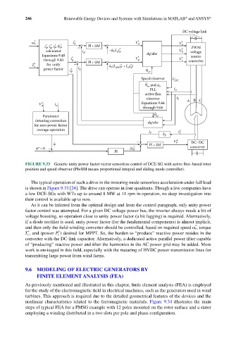
FIGURE 9.33 Generic unity power factor vector sensorless control of DCE-SG with active flux–based rotor
position and speed observer (PI+SM means proportional integral and sliding mode controller).
The typical operation of such a drive in the motoring mode sensorless acceleration under full load
is shown in Figure 9.33 [24]. The drive can operate in four quadrants. Though a few companies have
a few DCE-SGs with WTs up to around 8 MW at 11 rpm in operation, no deep investigation into
their control is available up to now.
As it can be inferred from the optimal design and from the control paragraph, only unity power
factor control was attempted. For a given DC voltage power bus, the inverter always needs a bit of
voltage boosting, so operation close to unity power factor (a bit lagging) is required. Alternatively,
if a diode rectifier is used, unity power factor (for the fundamental components) is almost implicit,
*
and then only the field-winding converter should be controlled, based on required speed ω r , torque
*
*
T e , and (power P e ) desired for MPPT. So, the burden to “produce” reactive power resides in the
converter with the DC-link capacitor. Alternatively, a dedicated active parallel power filter capable
of “producing” reactive power and filter the harmonics in the AC power grid may be added. More
work is envisaged in this field, especially with the maturing of HVDC power transmission lines for
transmitting large power from wind farms.
9.6 MODELING OF ELECTRIC GENERATORS BY
FINITE ELEMENT ANALYSIS (FEA)
As previously mentioned and illustrated in this chapter, finite element analysis (FEA) is employed
for the study of the electromagnetic field in electrical machines, such as the generators used in wind
turbines. This approach is required due to the detailed geometrical features of the devices and the
nonlinear characteristics related to the ferromagnetic materials. Figure 9.34 illustrates the main
steps of typical FEA for a PMSG example with 12 poles mounted on the rotor surface and a stator
employing a winding distributed in a two slots per pole and phase configuration.