Page 361 - Robot Builder's Bonanza
P. 361

330    BUILD ROBOTS WITH LEGS


                                                            to a servo, and the front legs, which
                                                            attach to the robot using a screw and
                                                            lock nut. You will make two of each style.
                                                            I’ve set the hole spacing for a  six- arm
                                                            “star” servo hub, common on Futaba
                                                            and  Futaba- style  standard- size servos. If
                                                            you use a different hub, you’ll need to
                                                            adjust the spacing of the holes. Drill out
                                                            the holes in the hub to accommodate the
                                                            4- 40 machine screws.
                                                              Use two 4- 40   1/2″ machine screws
                                                            and nuts to attach the servo hub to the
                                                            underside of the upper leg piece. See
                                                            Figure 27- 13 for a pictorial view of the
                                                            leg pieces, separate and assembled. Note
                                                            the extra chamfering added to the cor-
                                                            ners of the upper leg pieces. This isn’t
                                                            required, but it makes the legs look a bit
                                                            more streamlined.

                                                            CUT THE BASE PIECES

                                                            Follow the cutting and drilling guide in
                                                            Figure 27- 14 to prepare the base, middle
                                                            spar, middle leg servo mount, and the
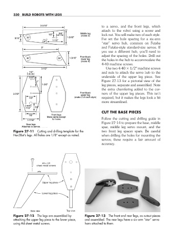
           Figure 27- 11  Cutting and drilling template for the   two front leg spacer spars. Be careful
           Hex3Bot’s legs. All holes are 1/8″ except as noted.  when drilling the holes for mounting the
                                                            servos; these require a fair amount of
                                                            accuracy.


                           #4 x 1/2
                        sheet metal screws


                           Upper leg piece


                           Lower leg piece


                     Side view           Top view
           Figure 27- 12  The legs are assembled by   Figure 27- 13  The front and rear legs, as cutout pieces
           attaching the upper leg piece to the lower piece,   and assembled. The rear legs have a  six- arm “star” servo
           using #4 sheet metal screws.            horn attached to them.


   27-chapter-27.indd   330                                                                     4/21/11   11:52 AM
   356   357   358   359   360   361   362   363   364   365   366