
Page 363 - Robot Builder's Bonanza
P. 363
332 BUILD ROBOTS WITH LEGS
5-1/2"
Front/rear
leg link
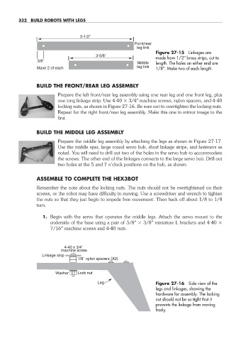
Figure 27- 15 Linkages are
3-5/8"
made from 1/2″ brass strips, cut to
3/8"
Middle length. The holes on either end are
Make 2 of each leg link 1/8″. Make two of each length.
BUILD THE FRONT/REAR LEG ASSEMBLY
Prepare the left front/rear leg assembly using one rear leg and one front leg, plus
one long linkage strip. Use 4- 40 3/4″ machine screws, nylon spacers, and 4- 40
locking nuts, as shown in Figure 27- 16. Be sure not to overtighten the locking nuts.
Repeat for the right front/rear leg assembly. Make this one in mirror image to the
first.
BUILD THE MIDDLE LEG ASSEMBLY
Prepare the middle leg assembly by attaching the legs as shown in Figure 27- 17.
Use the middle spar, large round servo hub, short linkage strips, and fasteners as
noted. You will need to drill out two of the holes in the servo hub to accommodate
the screws. The other end of the linkages connects to the large servo hub. Drill out
two holes at the 5 and 7 o’clock positions on the hub, as shown.
ASSEMBLE TO COMPLETE THE HEX3BOT
Remember the note about the locking nuts. The nuts should not be overtightened on their
screws, or the robot may have difficulty in moving. Use a screwdriver and wrench to tighten
the nuts so that they just begin to impede free movement. Then back off about 1/8 to 1/4
turn.
1. Begin with the servo that operates the middle legs. Attach the servo mount to the
underside of the base using a pair of 3/8″ 3/8″ miniature L brackets and 4- 40
7/16″ machine screws and 4- 40 nuts.
4-40 x 3/4"
machine screw
Linkage strip
1/8" nylon spacers (X2)
Washer Lock nut
Leg Figure 27- 16 Side view of the
legs and linkages, showing the
hardware for assembly. The locking
nut should not be so tight that it
prevents the linkage from moving
freely.
27-chapter-27.indd 332 4/21/11 11:52 AM