
Page 368 - Robot Builder's Bonanza
P. 368
CREATING X- Y SERVO JOINTS 337
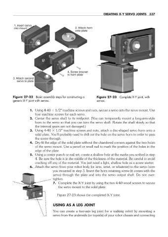
1. Insert servo
into mount 2. Attach horn
onto plate
4. Screw bracket
to horn plate
3. Attach second
servo to plate
Figure 27- 22 Basic assembly steps for constructing a Figure 27- 23 Complete X- Y joint, with
generic X- Y joint with servos. servos.
1. Using 4- 40 1/2″ machine screws and nuts, secure a servo into the servo mount. Use
four machine screws for each servo.
2. Center the servo shaft to its midpoint. (You can temporarily mount a long- arm- style
horn to the servo so that you can turn the servo shaft. Rotate the shaft slowly so that
the internal gears are not damaged.)
3. Using 4- 40 1/2″ machine screws and nuts, attach a disc- shaped servo horn onto a
solid plate. You’ll probably need to drill out the hole on the servo horn in order to pass
the screw through.
4. Dry- fit the edge of the solid plate without the chamfered corners against the two holes
of the servo mount. Use a pencil or small nail to mark the position of the holes in the
edge of the plate.
5. Using a center punch or nail set, create a shallow hole at the marks you scribed in step
4. Be sure the hole is in the middle of the thickness of the material. Be careful to avoid
cracking off any of the material. You just need a light, shallow hole as a screw starter.
6. Attach the servo from your robot body (or arm, wrist, or whatever) to the servo horn
you mounted in step 3. Insert the horn retaining screw (it comes with the
servo) through the plate and into the servo output shaft. Do not over-
tighten.
7. Complete the X- Y joint by using the two 4- 40 wood screws to secure
the servo mount to the solid plate.
Figure 27- 23 shows the completed X- Y joint.
USING AS A LEG JOINT
You can create a two- axis leg joint for a walking robot by mounting a
servo from the underside (or topside) of your robot chassis and connecting
27-chapter-27.indd 337 4/21/11 11:52 AM