
Page 367 - Robot Builder's Bonanza
P. 367
336 BUILD ROBOTS WITH LEGS
1-7/8"
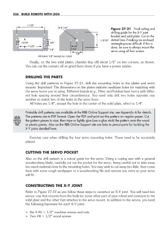
Drill 1/4" Figure 27- 21 Final cutting and
drilling guide for the X- Y joint
bracket and solid plate. Cut on the
1-3/16" dotted lines if making an enclosed
1/8"
13/16" 3/8" rectangle proves difficult. If this is
1-5/8" done, be sure to always mount the
1/8" 7/16"
servo using all four screws.
7/8"
All holes 1/8" except as noted
Finally, on the two solid plates, chamfer (lop off) about 1/2″ on two corners, as shown.
You can cut the corners off or grind them down if you have a power sander.
DRILLING THE PARTS
Using the drill patterns in Figure 27- 21, drill the mounting holes in the plates and servo
mounts. Important! The dimensions on the plates indicate candidate holes for matching with
the servo horns you’re using. Different brands (e.g., Hitec and Futaba) have horns with differ-
ent hole spacing around their circumference. You need only drill two holes opposite one
another to match two of the holes in the servo horn.
All holes are 1/8″, except the hole in the center of the solid plate, which is 1/4″.
Printable drill patterns are available at the RBB Online Support site; see Appendix A for details.
The patterns are in PDF format. Open the PDF and print out the pattern on regular paper. Cut
ON THE
the pattern pieces to size, then tape or lightly glue (use a glue stick) the pattern onto the wood
W E B or plastic pieces. Also on the RBB Online Support site are links to precut parts for building the
X- Y joints detailed here.
Exercise care when drilling the four servo mounting holes. These need to be accurately
placed.
CUTTING THE SERVO POCKET
Also on the drill pattern is a cutout guide for the servo. Using a coping saw with a general
woodworking blade, carefully cut out the pocket for the servo, being careful not to take away
too much material close to the mounting holes. You may wish to cut away too little, then come
back with some rough sandpaper or a woodworking file and remove any extra so your servo
will fit.
CONSTRUCTING THE X- Y JOINT
Refer to Figure 27- 22 as you follow these steps to construct an X- Y joint. You will need two
servos: one that mounts from the body (or some other part of your robot) and connects to the
solid plate and the other that attaches to the servo mount. In addition to the servos, you need
the following hardware for each X- Y joint:
• Six 4- 40 1/2″ machine screws and nuts
• Two #4 1/2″ wood screws
27-chapter-27.indd 336 4/21/11 11:52 AM