
Page 362 - Robot Builder's Bonanza
P. 362
BUILD A 3- SERVO HEXAPOD 331
Middle leg Front leg spacer spars
servo mount (make 2)
1-7/8" 3-1/2"
1/2"
2-11/16"
1/8" 13/16" 3/8"
1-5/8"
1/8"
Base
7"
3/8"
5-15/16"
1-7/8"
3"
3-1/2" 2" 2-11/16"
4-3/8"
3/4" 1-3/16"
See servo bracket
dimensions for
7/8"
cutting and drilling sizes
6-5/16"
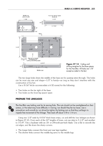
Figure 27- 14 Cutting and
1/2" 2-3/16" 2" drilling template for the base pieces
for the Hex3Bot. All holes are 1/8″
Middle spar
5/16" except as noted in the text.
The two large holes down the middle of the base are for passing wires through. The holes
can be most any size and shape—1/2″ is handy— as long as they don’t interfere with the
construction of the bot.
Use a 9/16″ bit (to accommodate a 6- 32 screw) for the following:
• Two holes on the far right of the base
• Two holes on the front leg spacer spars
PREPARE THE LINKAGES
The Hex3Bot uses locking nuts for its moving links. The nuts should not be overtightened on their
G screws, or the robot may have difficulty in moving; nor should they be too loose. Use a
screwdriver and wrench (or nut driver) to tighten the locking nuts so that they just begin to
impede free movement of the linkage. Then back off about 1/8 to 1/4 turn.
Using two 1/2″-wide by 0.016″-thick brass strips, cut and drill the four linkages as shown
in Figure 27- 15. From each of the 12″ lengths of brass, cut one strip to 5- 1/2″ and another
to 3- 5/8″. Use a hacksaw with an 18- or 24- tooth- per- inch blade. Use a file to smooth the
cut edges, and file down the sharp corners.
• The longer links connect the front and rear legs together.
• The shorter links connect the middle leg servo to the middle legs.
27-chapter-27.indd 331 4/21/11 11:52 AM