
Page 364 - Robot Builder's Bonanza
P. 364
BUILD A 3- SERVO HEXAPOD 333
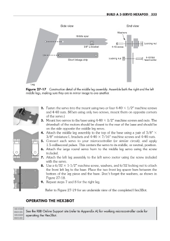
Side view End view
Washers
Middle spar
Locking nut
3/8" L-bracket 4-40 screw
4-40 flat
Locking nut
Short linkage strip head screw
Leg
Figure 27- 17 Construction detail of the middle leg assembly. Assemble both the right and the left
middle legs, making sure they are in mirror image to one another.
2. Fasten the servo into the mount using two or four 4- 40 1/2″ machine screws
and 4- 40 nuts. (When using only two screws, mount them on opposite corners
of the servo.)
3. Mount two servos to the base using 4- 40 1/2″ machine screws and nuts. The
driveshaft of the motors should be closest to the rear of the base and should be
on the side opposite the middle leg servo.
4. Attach the middle leg assembly to the top of the base using a pair of 3/8″
3/8″ miniature L brackets and 4- 40 7/16″ machine screws and 4- 40 nuts.
5. Connect each servo to your microcontroller (or similar circuit), and apply
1.5- millisecond pulses. This centers the servo to its middle, or neutral, position.
6. Attach the large round servo horn to the middle leg servo using the screw
included.
7. Attach the left leg assembly to the left servo motor using the screw included
with the servo.
8. Use a 6/32 1- 1/2″ machine screw, washers, and 6/32 locking nut to attach
the front left leg to the base. Place the two front leg spacer bars between the
bottom of the leg piece and the base. Don’t forget the washers, as shown in
Figure 27- 18.
9. Repeat steps 7 and 8 for the right leg.
Refer to Figure 27- 19 for an underside view of the completed Hex3Bot.
OPERATING THE HEX3BOT
101010
010101 See the RBB Online Support site (refer to Appendix A) for working microcontroller code for
101010 operating the Hex3Bot.
010101
27-chapter-27.indd 333 4/21/11 11:52 AM