
Page 378 - Robot Builder's Bonanza
P. 378
BUILD A FUNCTIONAL REVOLUTE COORDINATE ARM 347
BUILD THE BASE
The base of the arm consists of a 3″ ball bearing turntable (“lazy Susan”) mounted on
4- 1/2″-diameter round plastic, which serves as a bottom plate (this plate can be square if
that’s easier for you to cut). You can get this size turntable at better stocked hardware stores
and home improvement outlets, or via mail order. Search for 3″ lazy susan— I found mine for
under $2 sold through Amazon.
1. Begin by drilling four holes to mount the turntable. Use the turntable itself to mark the
holes in the center of the base. Once marked, drill the holes with a 1/8″ bit. Don’t
mount the turntable just yet.
2. Using the largest horn that comes with your servos, find two holes opposite one
another on the horn that are about 3/4″ to 1- 1/4″ apart. Use a 1/8″ bit to drill these
out.
3. Place the horn in the center of the 4″ bottom plate. Insert two 4- 40 1/2″ machine
screws through the horn and plate.
4. On the other side of the bottom plate, thread the screws through a pair of 3/4″ metal
corner angle brackets. Secure the screws with 4- 40 nuts.
5. Flip the bottom plate over again and mount the turntable using at least two screws on
opposite corners. To insert the screws you’ll need to spin the turntable so that all the
flanges (top and bottom) are exposed.
These construction plans don’t include mounting the fourth servo under the bottom plate. I’m
G leaving that up to you, based on where you want to put your arm. You can mount the arm on
top of a mobile robot (it should be at least 8″ to 10″ in size), or you can build a stationary arm
that operates within a confined space.
MOUNT THE JOINT SERVOS
You need to attach three servos into their mounts. Two sizes of mounts are used, as men-
tioned in “Building the Servo Mounts”: two regular- size mounts and one with a larger flange.
Secure the servos to their mounts using at least two screws, one on each corner of the motor.
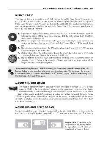
Each of the servos needs to be oriented a certain way within its mount. Refer to Figure
28- 9 for a guide. When viewed from the front of the servo, the output shaft of the motor
should be located as shown. Secure the servo within its mount using at least two 4- 40 1/2″
machine screws and nuts.
MOUNT SHOULDER SERVO TO BASE
Use the servo in the larger of the two mounts for the shoulder joint. This servo attaches to the
two 3/4″ corner angle brackets using 4- 40 1/2″ machine screws and nuts. The servo is
Figure 28- 9 Orientation of the
servo motors in the mounts. Attach
the motors to the mounts with their
output shafts oriented as shown.
28-chapter-28.indd 347 4/21/11 11:53 AM