
Page 375 - Robot Builder's Bonanza
P. 375
344 EXPERIMENTING WITH ROBOTIC ARMS
more difficult to use. In addition to the actuation cylinders themselves, a pump is required to
pressurize the air or oil, and valves are used to control the retraction or extension of the cyl-
inders. For the best results, you need a holding tank to stabilize the pressurization.
Build a Robotic Wrist
Sometimes a whole arm isn’t required. All the bot really needs is a hand (gripper) on the end
of a wrist- like mechanism that provides basic movement. The human wrist has 3 degrees of
freedom: it can twist (rotate) on the forearm, it can bend up and down, and it can rock from
side to side. You can add some or all of these degrees of freedom to a robotic hand.
You can create a basic 3- DOF wrist using the same X and Y components described in
Chapter 27, “Build Robots with Legs”; see the section “Building X- Y Servo Joints.” Plans are
provided for making compact parts for creating X- Y (pan/tilt, up- down/left- right) joints. By
stringing together a sequence of these joints you can build a compact wrist that provides a
remarkable amount of dexterity.
G You can attach a variety of grippers to the wrist mechanism described here. See Chapter 29,
“Experimenting with Robotic Grippers,” for some ideas and hands- on examples. Look especially
at the easy- to- build gripper described in “Tool Clamp Gripper” in Chapter 29.
Parts you’ll need:
• X- Y pieces cut to size, according to the plans in Chapter 27. (See step 1, below.)
• 16 4- 40 1/2″ machine screws and nuts
• 4 #6 3/4″ wood screws
1. Begin by cutting two pairs of X and Y pieces, as described in Chapter 27. To complete
the wrist you’ll need to make one more servo bracket. You’ll end up with a total of five
pieces: three servo brackets and two solid plates.
2. Using 4- 40 1/2″ machine screws and nuts, secure each of the three servos onto
servo mounts. Observe the orientation of the servo output shaft, along with the remain-
ing two mounting holes of the mount. When viewed from the front, the shaft should be
on the right and the two mounting holes should be on the bottom. When finished, you
will have three servos in three mounts.
3. Using 4- 40 1/2″ machine screws and nuts, attach a disc- shaped servo horn on a
solid plate. Repeat for the second plate. When finished, you will have two servo horns
on two plates.
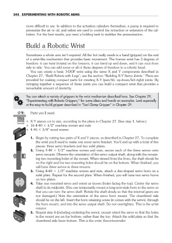
4. Take one mounted servo and orient as shown (holes facing the top). Center the servo
shaft to its midpoint. (You can temporarily mount a long- arm- style horn to the servo so
that you can turn the servo shaft. Rotate the shaft slowly so that the internal gears are
not damaged.) Note the orientation of the servo horn mount. The chamfered side
should be on the left. Insert the horn retaining screw (it comes with the servo), through
the horn mount, and into the servo output shaft. Do not overtighten. This is the wrist
rotator.
5. Repeat step 4 (including centering the servo), except orient the servo so that the holes
in the mount are on the bottom, rather than the top. Attach the solid plate so that the
chamfered side faces bottom. This is the wrist flexor/extender.
28-chapter-28.indd 344 4/21/11 11:53 AM