
Page 377 - Robot Builder's Bonanza
P. 377
346 EXPERIMENTING WITH ROBOTIC ARMS
You will need four standard- size R/C servo motors. For added strength, select servos with
a torque of no less than 45 oz- in; 65 to 85 oz- in is preferable. On most servos, the higher
the torque, the slower the servo turns, so bear this in mind when selecting the motors for
your arm.
To complete the arm, you’ll need:
• 1 12″ length of 3/8″ U- channel extruded aluminum
• 1 3″ ball bearing turntable
• 1 small piece (about 12″ 8″ ) 1/4″ aircraft- grade plywood or PVC plastic
• 1 pair of small 3/4″ corner angle brackets
• Small assortment of 4- 40 machine screws and nuts
MAKE THE SERVO MOUNTS
The robotic arm uses two types of servo mounts and one general- purpose (and optional) solid
plate for attaching to the shaft of the servo. The smaller mount and plate are described in the
“Building X- Y Servo Joints” section of Chapter 27, “Building Robots with Legs.” You need
two small mounts and one solid plate. You also need one slightly larger version of the servo
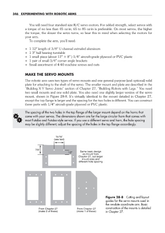
mount, shown in Figure 28- 8. It’s virtually identical to the mount detailed in Chapter 27,
except the top flange is larger and the spacing for the two holes is different. You can construct
these parts with 1/4″ aircraft- grade plywood or PVC plastic.
The spacing of the two holes in the top flange of the larger mount depend on the horns that
G come with your servos. The dimensions shown are for the large circular horn that comes with
most Futaba and Futaba- style servos. If you use a different servo and horn, the hole spacing
may be slightly different; adjust the spacing of the holes in the top flange accordingly.
15/16"
(see text)
7/8"
1/2" Same basic design
as mount from
Chapter 27, but larger
mount area and
different hole spacing
Figure 28- 8 Cutting and layout
guides for the servo mounts used in
the revolute coordinate arm. Basic
From Chapter 27 From Chapter 27 construction of the mounts is detailed
(make 2 of these) (make 1 of these) in Chapter 27.
28-chapter-28.indd 346 4/21/11 11:53 AM