
Page 379 - Robot Builder's Bonanza
P. 379
348 EXPERIMENTING WITH ROBOTIC ARMS
oriented so that its mounting flange points toward the base. The backside of the motor is over
the centerline of the base.
CONSTRUCT UPPER ARM
Make an upper arm (the part of the arm between shoulder and elbow) from a 6″ length of
3/8″ aluminum U- channel. Cut with a hacksaw, and file down the ends to remove any burrs.
Then:
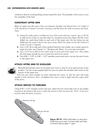
1. Using the small round or double- arm horn that comes with your servos, use a 1/8″ bit
to drill out two holes on opposite sides for mounting screws (see Figure 28- 10). Once
drilled out, mark three holes on each end of the upper arm: the two holes you just
drilled and the center hole for the servo screw. Place the marks on the flat (“bottom”)
of the U in the U- channel.
2. Use a 1/8″ bit to drill each of the marked holes (for best results, use a center punch to
begin the hole— see Chapter 11, “Working with Metal,” for more tips and tricks).
3. Use a 1/4″ bit to drill out the center hole on each end of the upper arm. This makes
the hole large enough for you to insert the servo horn screw.
4. Use 4- 40 3/8″ or 4- 40 1/2″ machine screws and nuts to secure the servo horns
to the upper arm.
ATTACH UPPER ARM TO SHOULDER
Manually (and slowly) rotate the shoulder joint motor so that it is at its approximate center
position. Use the screw supplied with the servo to attach the shoulder joint motor to the
bottom of the upper arm.
Point the arm piece straight up when attaching the motor, so that the joint will rotate
equally in both directions. Don’t overtighten the screw or else it might strip the output shaft
of the servo.
ATTACH SERVOS TO FOREARM
Using 4- 40 1/2″ machine screws and nuts, attach the two servos (the ones in the smaller
mounts) to the forearm. Be sure to orient the servos so that one faces the “front” of the arm,
and the other the back, as shown.
Drill out (1/8" bit)
Drill out (1/8" bit)
Figure 28- 10 Drill out the holes in a servo horn
for the base servo motor. For best results, pick holes
in the horn that are about 1″ apart.
28-chapter-28.indd 348 4/21/11 11:53 AM