
Page 384 - Robot Builder's Bonanza
P. 384
TWO- PINCHER GRIPPER 353
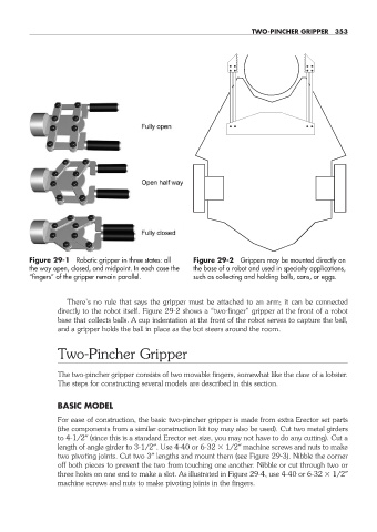
Figure 29- 1 Robotic gripper in three states: all Figure 29- 2 Grippers may be mounted directly on
the way open, closed, and midpoint. In each case the the base of a robot and used in specialty applications,
“fingers” of the gripper remain parallel. such as collecting and holding balls, cans, or eggs.
There’s no rule that says the gripper must be attached to an arm; it can be connected
directly to the robot itself. Figure 29- 2 shows a “two- finger” gripper at the front of a robot
base that collects balls. A cup indentation at the front of the robot serves to capture the ball,
and a gripper holds the ball in place as the bot steers around the room.
Two- Pincher Gripper
The two- pincher gripper consists of two movable fingers, somewhat like the claw of a lobster.
The steps for constructing several models are described in this section.
BASIC MODEL
For ease of construction, the basic two- pincher gripper is made from extra Erector set parts
(the components from a similar construction kit toy may also be used). Cut two metal girders
to 4- 1/2″ (since this is a standard Erector set size, you may not have to do any cutting). Cut a
length of angle girder to 3- 1/2″. Use 4- 40 or 6- 32 1/2″ machine screws and nuts to make
two pivoting joints. Cut two 3″ lengths and mount them (see Figure 29- 3). Nibble the corner
off both pieces to prevent the two from touching one another. Nibble or cut through two or
three holes on one end to make a slot. As illustrated in Figure 29- 4, use 4- 40 or 6- 32 1/2″
machine screws and nuts to make pivoting joints in the fingers.
29-chapter-29.indd 353 4/21/11 11:53 AM