
Page 385 - Robot Builder's Bonanza
P. 385
354 EXPERIMENTING WITH ROBOTIC GRIPPERS
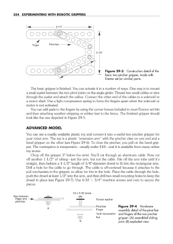
4 1/2"
Finger Pivot bar
3 1/2"
3"
Figure 29- 3 Construction detail of the
basic two- pincher gripper, made with
Erector set (or similar) parts.
The basic gripper is finished. You can actuate it in a number of ways. One way is to mount
a small eyelet between the two pivot joints on the angle girder. Thread two small cables or wire
through the eyelet and attach the cables. Connect the other end of the cables to a solenoid or
a motor shaft. Use a light- compression spring to force the fingers apart when the solenoid or
motor is not activated.
You can add pads to the fingers by using the corner braces included in most Erector set kits
and then attaching weather stripping or rubber feet to the brace. The finished gripper should
look like the one depicted in Figure 29- 5.
ADVANCED MODEL
You can use a readily available plastic toy and convert it into a useful two- pincher gripper for
your robot arm. The toy is a plastic “extension arm” with the pincher claw on one end and a
hand gripper on the other (see Figure 29- 6). To close the pincher, you pull on the hand grip-
per. The contraption is inexpensive— usually under $10—and it is available from many online
toy stores.
Chop off the gripper 3″ below the wrist. You’ll cut through an aluminum cable. Now cut
off another 1- 1/2″ of tubing— just the arm, but not the cable. File off the arm tube until it’s
straight, then fashion a 1- 1/2″ length of 3/4″-diameter dowel to fit into the rectangular arm.
Drill a hole for the cable to go through. The cable is off- centered because it attaches to the
pull mechanism in the gripper, so allow for this in the hole. Place the cable through the hole,
push the dowel at least 1/2″ into the arm, and then drill two small mounting holes to keep the
dowel in place (see Figure 29- 7). Use 6- 32 3/4″ machine screws and nuts to secure the
pieces.
1/2 x 6-32 screw
Gap between
finger and Fender washer
pivot bar
Pivot bar Figure 29- 4 Hardware
A
Finger assembly detail of the pivot bar
Tooth lockwasher and fingers of the two- pincher
Nut gripper: (A) assembled sliding
B joint; (B) exploded view.
29-chapter-29.indd 354 4/21/11 11:53 AM