
Page 380 - Robot Builder's Bonanza
P. 380
BUILD A FUNCTIONAL REVOLUTE COORDINATE ARM 349
• The output shaft of the servo that faces the front (same side as the open part of the
U- channel) should be on the right side.
• The output shaft of the servo that faces the back (flat part of the U- channel) should be on
the left side. Refer to the completed pictures of the arm to see how the servos are oriented.
MOUNT UPPER ARM TO ELBOW
Manually (and slowly) rotate the shoulder joint motor so that it is at its approximate center
position. Use the screw supplied with the servo to attach the elbow joint motor to the top
of the upper arm. Don’t overtighten the screw or else it might strip the output shaft of
the servo. As you did with the shoulder motor, mount the arm piece pointing straight up.
That way the joint will rotate equally in both directions.
ATTACH WRIST
Attach the solid plate to the wrist joint motor. From this plate you can mount a gripper to the
arm. (If your gripper already has a means to attach directly to the servo motor you can dis-
pense with the solid plate.)
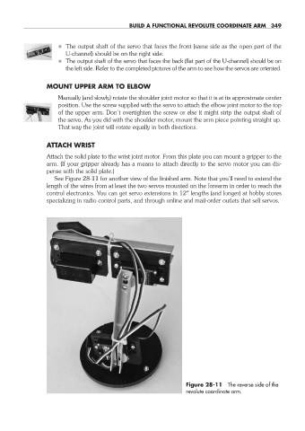
See Figure 28- 11 for another view of the finished arm. Note that you’ll need to extend the
length of the wires from at least the two servos mounted on the forearm in order to reach the
control electronics. You can get servo extensions in 12″ lengths (and longer) at hobby stores
specializing in radio control parts, and through online and mail- order outlets that sell servos.
Figure 28- 11 The reverse side of the
revolute coordinate arm.
28-chapter-28.indd 349 4/21/11 11:53 AM