
Page 389 - Robot Builder's Bonanza
P. 389
358 EXPERIMENTING WITH ROBOTIC GRIPPERS
ATTACH SERVO TO THE MOUNT
Using 4- 40 1/2″ machine screws and nuts, attach a standard- size servo to the gripper
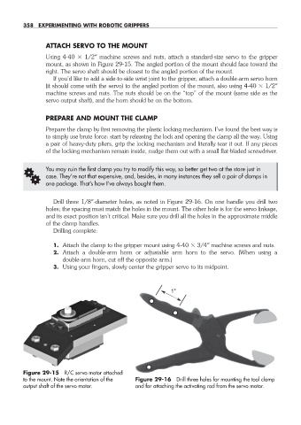
mount, as shown in Figure 29- 15. The angled portion of the mount should face toward the
right. The servo shaft should be closest to the angled portion of the mount.
If you’d like to add a side- to- side wrist joint to the gripper, attach a double- arm servo horn
(it should come with the servo) to the angled portion of the mount, also using 4- 40 1/2″
machine screws and nuts. The nuts should be on the “top” of the mount (same side as the
servo output shaft), and the horn should be on the bottom.
PREPARE AND MOUNT THE CLAMP
Prepare the clamp by first removing the plastic locking mechanism. I’ve found the best way is
to simply use brute force: start by releasing the lock and opening the clamp all the way. Using
a pair of heavy- duty pliers, grip the locking mechanism and literally tear it out. If any pieces
of the locking mechanism remain inside, nudge them out with a small flat- bladed screwdriver.
G You may ruin the first clamp you try to modify this way, so better get two at the store just in
case. They’re not that expensive, and, besides, in many instances they sell a pair of clamps in
one package. That’s how I’ve always bought them.
Drill three 1/8″-diameter holes, as noted in Figure 29- 16. On one handle you drill two
holes; the spacing must match the holes in the mount. The other hole is for the servo linkage,
and its exact position isn’t critical. Make sure you drill all the holes in the approximate middle
of the clamp handles.
Drilling complete:
1. Attach the clamp to the gripper mount using 4- 40 3/4″ machine screws and nuts.
2. Attach a double- arm horn or adjustable arm horn to the servo. (When using a
double- arm horn, cut off the opposite arm.)
3. Using your fingers, slowly center the gripper servo to its midpoint.
1"
Figure 29- 15 R/C servo motor attached
to the mount. Note the orientation of the Figure 29- 16 Drill three holes for mounting the tool clamp
output shaft of the servo motor. and for attaching the activating rod from the servo motor.
29-chapter-29.indd 358 4/21/11 11:53 AM