
Page 208 - Robot Builders Source Book - Gordon McComb
P. 208
196 Feedback Sensors
Here,
A/// = strain value,
AR = resistance increment due to strain, and
R = initial resistance of the gauge.
Modern devices have k values of several hundred.
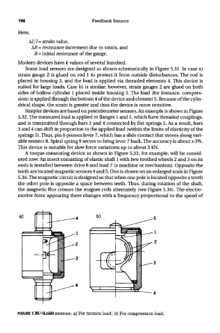
Some load sensors are designed as shown schematically in Figure 5.31. In case a)
strain gauge 2 is glued on rod 1 to protect it from outside disturbances. The rod is
placed in housing 3, and the load is applied via threaded elements 4. This device is
suited for large loads. Case b) is similar; however, strain gauges 2 are glued on both
sides of hollow cylinder 1 placed inside housing 3. The load (for instance, compres-
sion) is applied through the bottom 4 of the device and element 5. Because of the cylin-
drical shape, the strain is greater and thus the device is more sensitive.
Simpler devices are based on potentiometer sensors. An example is shown in Figure
5.32. The measured load is applied to flanges 1 and 2, which have threaded couplings,
and is transmitted through bars 3 and 4 connected by flat springs 5. As a result, bars
3 and 4 can shift in proportion to the applied load (within the limits of elasticity of the
springs 5). Thus, pin 6 presses lever 7, which has a slide contact that moves along vari-
able resistor 8. Spiral spring 9 serves to bring lever 7 back. The accuracy is about ± 3%.
This device is suitable for slow force variations up to about 3 kN.
A torque-measuring device as shown in Figure 5.33, for example, will be consid-
ered now. An insert consisting of elastic shaft 1 with two toothed wheels 2 and 3 on its
ends is installed between drive 6 and load 7 (a machine or mechanism). Opposite the
teeth are located magnetic sensors 4 and 5. One is shown on an enlarged scale in Figure
5.34. The magnetic circuit is designed so that when one pole is located opposite a tooth
the other pole is opposite a space between teeth. Thus, during rotation of the shaft,
the magnetic flux crosses the magnet coils alternately (see Figure 5.34). The electro-
motive force appearing there changes with a frequency proportional to the speed of
TEAM LRN
FIGURE 5.31 Load sensors: a) For tension load; b) For compression load.