
Page 210 - Robot Builders Source Book - Gordon McComb
P. 210
198 Feedback Sensors
rotation. When no torque is applied to shaft 1, the teeth pass the magnets simultane-
ously. However, when the shaft is loaded, a rotational shift between the two wheels
occurs. As a result, there is a phase shift between the electromotive forces, which is
proportional to the torque. The phase shift does not depend on the speed of rotation.
The accuracy of the device depends on the properties of shaft 1's material and the sta-
bility, and is about 0.1-0.2% at constant temperatures.
Another application of force measurements is in pressure sensors, which are used
either for direct pressure indication or for obtaining the pressure as secondary infor-
mation, for instance, in pneumatic devices for dimension measurements, or for flow-
rate measurements with Venturi or Pitot devices. Figure 5.35 shows a typical pressure
sensor. The pressure p affects membrane 1 which presses against flat spring 2 due to
the pusher 4. The latter has strain gauges 3 glued to it. The action of this device is
2
obvious. The accuracy is about ±1.5%, and the range is 0.1-0.6 MN/m . Other elastic
pressure-sensitive elements can also be used in combination with appropriately glued
strain-gauge sets, e.g., bellows, Bourdon tubes, etc. In cases where the elastic element
undergoes relatively large displacements in response to the pressure, appropriate
sensors without amplifiers can be used.
2
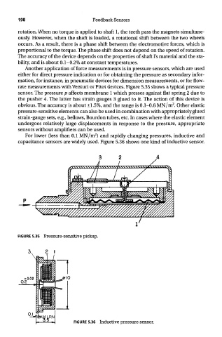
For lower (less than 0.1 MN/m ) and rapidly changing pressures, inductive and
capacitance sensors are widely used. Figure 5.36 shows one kind of inductive sensor.
FIGURE 5.35 Pressure-sensitive pickup.
TEAM LRN
FIGURE 5.36 Inductive pressure sensor.