
Page 212 - Robot Builders Source Book - Gordon McComb
P. 212
200 Feedback Sensors
5.4 Temperature Sensors
We consider three groups of phenomena used in the design of temperature sensors:
1. Electrical phenomena,
2. Thermal expansion,
3. Optical phenomena.
1. Electrical sensors are based mainly on thermoresistors and thermocouples. In
addition, an electroacoustic method, based on the dependence of the speed of sound
upon gas temperature, and a thermonoise method are in use.
1
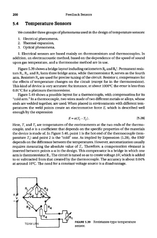
Figure 5.39 shows a bridge layout including ratiometers RQ and Ro . Permanent resis-
tors R lf R 2, and R 3 form three bridge arms, while thermoresistor R t serves as the fourth
arm. Resistors R 4 are used for precise tuning of the circuit. Resistor r t compensates for
the effects of temperature changes on the circuit (except for in the thermoresistor).
This kind of device is very accurate: for instance, at about 1000°C the error is less than
0.01°C for a platinum thermoresistor.
Figure 5.40 shows a possible layout for a thermocouple, with compensation for its
"cold arm." In a thermocouple, two wires made of two different metals or alloys, whose
ends are welded together, are used. When placed in environments with different tem-
peratures the weld points create an electromotive force E, which is described well
enough by the expression
Here, 7\ and T 2 are temperatures of the environments at the two ends of the thermo-
couple, and a is a coefficient that depends on the specific properties of the materials
the device is made of. In Figure 5.40, point 1 is the hot end of the thermocouple (tem-
perature 7\) and point 2 is the "cold" one. As implied by Expression (5.28), the EMF
depends on the difference between the temperatures. However, automatization usually
requires measuring the absolute value of 7\. Therefore, a compensation element is
inserted between points a-a in the design. This compensator is a bridge in which one
arm is thermoresistor R t. The circuit is tuned so as to create voltage AV, which is added
to or subtracted from that created by the thermocouple. The accuracy is about 0.04%
at around 10°C. The need for a constant voltage source is a disadvantage.
FIGURE 5.39 Resistance-type temperature
TEAM LRN
sensor.