
Page 133 - Schaum's Outline of Theory and Problems of Electric Circuits
P. 133
WAVEFORMS AND SIGNALS
122
Fig. 6-20 [CHAP. 6
6
Let v designate the voltage across the parallel RC combination. The current in R is i R ¼ v=R ¼ 10 v.
During the pulse, i R remains negligible because v cannot exceed 1 V and i R remains under 1 mA. Therefore,
þ
it is reasonable to assume that during the pulse, i C ¼ 1 A and consequently vð0 Þ¼ 1 V. For t > 0, from
application of KVL around the RC loop we get
dv þ
v þ ¼ 0; vð0 Þ¼ 1V ð41Þ
dt
t
The only solution to (41)is v ¼ e t for t > 0or vðtÞ¼ e uðtÞ for all t. For all practical purposes, i s can be
t
considered an impulse of size 10 6 A, and then v ¼ e uðtÞ (V) is called the response of the RC combination
to the current impulse.
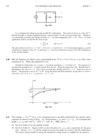
6.20 Plot the function vðtÞ which varies exponentially from 5 V at t ¼ 0to12 V at t ¼1 with a time
constant of 2 s. Write the equation for vðtÞ.
Identify the initial point A (t ¼ 0 and v ¼ 5Þ and the asymptote v ¼ 12 in Fig. 6-21. The tangent at A
intersects the asymptote at t ¼ 2, which is point B on the line. Draw the tangent line AB. Identify point C
belonging to the curve at t ¼ 2. For a more accurate plot, identify point D at t ¼ 4. Draw the curve as
shown. The equation is vðtÞ¼ Ae t=2 þ B. From the initial and final conditions, we get vð0Þ¼ A þ B ¼ 5
and vð1Þ ¼ B ¼ 12 or A ¼ 7, and vðtÞ¼ 7e t=2 þ 12.
Fig. 6-21
6.21 The voltage v ¼ V 0 e ajtj for a > 0 is connected across a parallel combination of a resistor and a
capacitor as shown in Fig. 6-22(a). (a) Find currents i C , i R , and i ¼ i C þ i R . (b) Compute and
graph v, i C , i R , and i for V 0 ¼ 10 V, C ¼ 1 mF, R ¼ 1M
, and a ¼ 1.
(a) See (a) in Table 6-3 for the required currents.
(b) See (b) in Table 6-3. Figures 6-22(b)–(e) show the plots of v, i C , i R , and i, respectively, for the given
data. During t > 0, i ¼ 0, and the voltage source does not supply any current to the RC combination.
The resistor current needed to sustain the exponential voltage across it is supplied by the capacitor.