Page 131 - Schaum's Outline of Theory and Problems of Electric Circuits
P. 131

[CHAP. 6
                                              WAVEFORMS AND SIGNALS
               120
                         The rms value of v 2 ðtÞ can also be derived directly.  Because of the squaring operation, a full-rectified
                                                                                    p
                                                                                      ffiffiffi
                     cosine function has the same rms value as the cosine function itself, which is V m = 2.
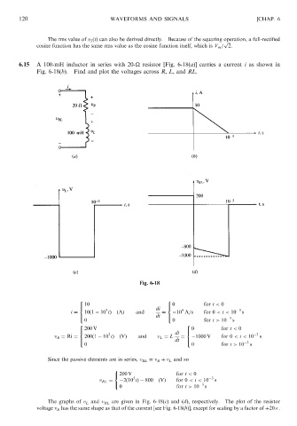
               6.15  A 100-mH inductor in series with 20-
 resistor [Fig. 6-18(a)] carries a current i as shown in
                     Fig. 6-18(b).  Find and plot the voltages across R, L, and RL.


                                                        Fig. 6-18

                                    8                            8
                                    >  10                        >  0         for t < 0
                                                                 <
                                    <
                                                                      4
                                             3
                                 i ¼  10ð1   10 tÞ  ðAÞ  and  di  ¼   10 A=s  for 0 < t < 10  3  s
                                    >                         dt  >                   3
                                                                 :
                                    :
                                     0                             0          for t > 10  s
                                    8                                   8
                                    >  200 V                            >  0        for t < 0
                                    <
                                                                        <
                                             3
                           v R ¼ Ri ¼  200ð1   10 tÞ  ðVÞ  and  v L ¼ L  di  ¼   1000 V  for 0 < t < 10  3  s
                                    >                               dt  >                   3
                                                                        :
                                    :
                                     0                                    0         for t > 10  s
                         Since the passive elements are in series, v RL ¼ v R þ v L and so
                                               8
                                               <  200 V             for t < 0
                                                      5
                                          v RL ¼   2ð10 tÞ  800  ðVÞ  for 0 < t < 10  3  s
                                               :                             3
                                                 0                  for t > 10  s
                         The graphs of v L and v RL are given in Fig. 6-18(c) and (d), respectively.  The plot of the resistor
                     voltage v R has the same shape as that of the current [see Fig. 6-18(b)], except for scaling by a factor of þ20 .
   126   127   128   129   130   131   132   133   134   135   136