
Page 52 - Schaum's Outline of Theory and Problems of Electric Circuits
P. 52
CHAP. 4]
32
2 ANALYSIS METHODS 3 2 3 41
1 1 1 1
þ þ V 1 V =R A
a
6 76 7 6 7
6 R A R B R C R C 76 7 ¼ 6 7
4 1 1 1 1 54 5 4 5
þ þ V 2 V b =R E
R C R C R D R E
Note the symmetry of the coefficient matrix. The 1,1-element contains the sum of the reciprocals of
all resistances connected to note 1; the 2,2-element contains the sum of the reciprocals of all resistances
connected to node 2. The 1,2- and 2,1-elements are each equal to the negative of the sum of the
reciprocals of the resistances of all branches joining nodes 1 and 2. (There is just one such branch
in the present circuit.)
On the right-hand side, the current matrix contains V a =R A and V b =R E , the driving currents. Both
these terms are taken positive because they both drive a current into a node. Further discussion of the
elements in the matrix representation of the node voltage equations is given in Chapter 9, where the
networks are treated in the sinusoidal steady state.
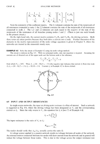
EXAMPLE 4.5 Solve the circuit of Example 4.2 using the node voltage method.
The circuit is redrawn in Fig. 4-5. With two principal nodes, only one equation is required. Assuming the
currents are all directed out of the upper node and the bottom node is the reference,
V 1 20 V 1 V 1 8
þ þ ¼ 0
5 10 2
from which V 1 ¼ 10 V. Then, I 1 ¼ð10 20Þ=5 ¼ 2 A (the negative sign indicates that current I 1 flows into node
1); I 2 ¼ð10 8Þ=2 ¼ 1A; I 3 ¼ 10=10 ¼ 1 A. Current I 3 in Example 4.2 is shown dotted.
Fig. 4-5
4.5 INPUT AND OUTPUT RESISTANCES
In single-source networks, the input or driving-point resistance is often of interest. Such a network
is suggested in Fig. 4-6, where the driving voltage has been designated as V 1 and the corresponding
current as I 1 . Since the only source is V 1 , the equation for I 1 is [see (7) of Example 4.4]:
11
I 1 ¼ V 1
R
The input resistance is the ratio of V to I :
1
1
R
R input;1 ¼
11
The reader should verify that R = 11 actually carries the units
.
A voltage source applied to a passive network results in voltages between all nodes of the network.
An external resistor connected between two nodes will draw current from the network and in general will
reduce the voltage between those nodes. This is due to the voltage across the output resistance (see