Page 57 - Schaum's Outline of Theory and Problems of Electric Circuits
P. 57

ANALYSIS METHODS
               46


                                                        Fig. 4-13                               [CHAP. 4


                                                     0
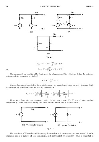
                                               V ab ¼ V ¼ 20    30  ð3Þ¼ 10 V
                                                              9

                                                          30
                                                      0
               or                              V ab ¼ V ¼    6   10 ¼ 10 V
                                                          9
                                0
                   The resistance R can be obtained by shorting out the voltage sources [Fig. 4.13(c)] and finding the equivalent
               resistance of this network at terminals ab:
                                                          ð3Þð6Þ
                                                     0
                                                   R ¼ 3 þ     ¼ 5
                                                            9
                   When a short circuit is applied to the terminals, current I s:c: results from the two sources.  Assuming that it
               runs through the short from a to b, we have, by superposition,
                                                  2        3         2       3

                                         0
                                                                     4
                                                  4
                                                           5
                                   I s:c: ¼ I ¼  6  6  20  7     3   6   10  7
                                                                             5 ¼ 2A
                                             6 þ 3     ð3Þð6Þ   3 þ 3    ð3Þð3Þ
                                                    3 þ               6 þ
                                                        9                  6
                                                                                   0
                                                                                0
                   Figure 4-14 shows the two equivalent circuits.  In the present case, V , R , and I  0  were obtained
               independently. Since they are related by Ohm’s law, any two may be used to obtain the third.


                                                        Fig. 4-14

                   The usefulness of The ´ venin and Norton equivalent circuits is clear when an active network is to be
               examined under a number of load conditions, each represented by a resistor.  This is suggested in
   52   53   54   55   56   57   58   59   60   61   62